
HP EliteDisplay E190i Manuel

Maintenance and Service Guide
E190i model
SUMMARY
This guide provides information about spare parts, removal and replacement of parts, diagnostic tests, problem
troubleshooting, and more.

© Copyright 2021 HP Development
Company, L.P.
AMD is a trademark of Advanced Micro
Devices, Inc. Bluetooth is a trademark owned
by its proprietor and used by HP Inc. under
license. NVIDIA is a trademark and/or
registered trademark of NVIDIA Corporation
in the U.S. and other countries. USB Type-C
and USB-C are registered trademarks of USB
Implementers Forum. DisplayPort and the
DisplayPort logo are trademarks owned by
the Video Electronics Standards Association
(VESA) in the United States and other
countries.
The information contained herein is subject
to change without notice. The only
warranties for HP products and services are
set forth in the express warranty statements
accompanying such products and services.
Nothing herein should be construed as
constituting an additional warranty. HP shall
not be liable for technical or editorial errors
or omissions contained herein.
First Edition: January 2022
Document Part Number: 734057-E190i-
MSG-V1
Assembly part number: 734057-001
Product notice
Only trained service personnel familiar with
this product should service it. Before
performing any maintenance or service, be
sure to read “Important Safety Information”.

iii
Table of Contents
1Getting started ............................................................................................................................................................. 1
Important safety information................................................................................................................................ 1
Important service information and precautions .................................................................................................... 1
RoHS (2002/95/EC) requirements.......................................................................................................................... 2
General descriptions .............................................................................................................................................. 2
Firmware updates .................................................................................................................................................. 2
Before returning the repaired product to the customer ....................................................................................... 2
2Monitor features........................................................................................................................................................... 3
Features ................................................................................................................................................................. 3
Front components.................................................................................................................................................. 5
Rear and side components..................................................................................................................................... 6
Locating the serial number and product number .................................................................................................. 7
3Illustrated parts catalog .............................................................................................................................................. 8
How to order parts ................................................................................................................................................. 9
4Removal and replacement procedures...................................................................................................................... 11
Preparation for disassembly................................................................................................................................ 11
Rear Cover ............................................................................................................................................................ 11
Power board......................................................................................................................................................... 14
Connector repair .................................................................................................................................................. 15
D-Sub connector P302.............................................................................................................................. 17
DVI connector P303 .................................................................................................................................. 17
DP connector P302 ................................................................................................................................... 17
USB-B connector P202 ............................................................................................................................. 18
USB-A connector P2A2, P2A3................................................................................................................... 18
Function test ........................................................................................................................................................ 19
Support and troubleshooting .............................................................................................................................. 19
Index..................................................................................................................................................................... 21

1
1Getting started
Read this chapter to learn about safety information and where to find additional HP resources.
Important safety information
Carefully read the cautions and notes within this document to minimize the risk of personal injury to service
personnel. The cautions and notes are not exhaustive. Proper service methods are important to the safe, reliable
operation of equipment. Improper service methods can damage equipment.
The service procedures recommended and described in this service manual provide effective methods of
performing service operations. Service engineers should have prior repair knowledge and experience as well as
appropriate training for the product before performing service procedures.
●Be sure your working environment is dry and clean and meets all government safety requirements.
●Be sure that other persons are safe while you are servicing the product.
●Do not perform any action that can cause a hazard to the customer or make the product unsafe.
●Use proper safety devices to ensure your personal safety.
●Always use approved tools and test equipment for servicing.
●Never assume the product’s power is disconnected from the main power supply. Check that it is
disconnected before opening the product’s cabinet.
●Modules containing electrical components are sensitive to electrostatic discharge (ESD). Follow ESD
safety procedures while handling these parts.
●Some products contain more than one battery. Do not disassemble or expose a battery to high
temperatures, such as throwing into fire, or the battery may explode.
●Refer to government requirements for battery recycling or disposal.
This information provides general service information for the monitor. Adherence to the procedures and
precautions is essential for proper service.
IMPORTANT: Only trained service personnel who are familiar with this HP product should perform service or
maintenance for it. Before performing any service or maintenance, personnel must read the important safety
information.
IMPORTANT: You must disconnect the power cord from the power source before opening the monitor to
prevent component damage.
Important service information and precautions
●Repair must be performed by professional service technicians in a repair center. End users should not
perform these procedures.
●Please note during servicing that the primary side is the high voltage area.
●This monitor meets ROHS requirements. Be sure to use lead-free solder wire when soldering.
●If you must change a capacitor, be sure to match the polarity as printed on the PCB.
●If you must replace a capacitor, make sure the specification and part number match the BOM and

2
location.
●If you must replace a capacitor, insert new parts carefully to avoid a short circuit caused by the near
pin.
●Do not get the board wet. Water and moisture can cause a short circuit that causes malfunctions.
●To avoid damage, be sure to use lead-free solder.
●When soldering, work quickly to avoid overheating the circuit board.
●Keep the soldering iron tip clean and well tinned when replacing parts.
●After repair, perform a close inspection of the circuit board to confirm it is in good condition.
●After repair, perform a function test to confirm the power supply is working properly.
ERP Lot5 requirement
1. A professional repairer must have the technical competence to repair electronic displays and comply with
the applicable regulations for repairers of electrical equipment in the Member States where the repairer
operates. Reference to an official registration system as professional repairer, where such a system exists
in the Member States, shall be accepted as proof of compliance.
2. A professional repairer must have insurance that covers liabilities resulting from repairs, regardless of
whether required by the Member State.
RoHS (2002/95/EC) requirements
Applied to all countries that require RoHS.
The RoHS (Restriction of Hazardous Substance in Electrical and Electronic Equipment Directive) is a legal
requirement by the EU (European Union) for the global electronics industry sold in the EU and other countries.
Any electrical and electronics products launched in the market after June 2006 should meet this RoHS
requirement. Products launched in the market before June 2006 are not required to be compliant with RoHS
parts. If the original parts are not RoHS complaint, the replacement parts can be non-ROHS complaint. If the
original parts are RoHS compliant, the replacement parts MUST be RoHS complaint.
If product service or maintenance requires replacing parts, confirm the RoHS requirement before replacement.
General descriptions
This manual contains general information. There are two levels of service:
Level 1: Cosmetic/appearance/alignment service
Level 2: Circuit board or standard parts replacement
Firmware updates
Firmware updates for the monitor are available at support.hp.com. If no firmware is posted, the monitor does
not need a firmware update.
Before returning the repaired product to the customer
Perform an AC leakage current check on exposed metallic parts to be sure the product is safe to operate
without the potential of electrical shock. Do not use a line isolation transformer during this check.
Measurements that are not within specified limits present a possible shock hazard. You must check and repair
the product before returning it to the customer.

3
2Monitor features
This chapter provides an overview of the monitor’s features.
Features
Depending on the model, your monitor might include the following features:
Display features
●EliteDisplay E190i model, 47.99 cm (18.89–inch) diagonal viewable area display with 1280 x1024
resolution, plus full-screen support for lower resolutions: includes custom scaling for maximum
image size
●Non-glare panel with an LED backlight
●Wide viewing angle to allow viewing from a sitting or standing position, or moving from side to side
●Tilt capabilities
●Pivot capability to rotate display to portrait mode
●Swivel and height adjustment capabilities
●Removable stand for flexible monitor head mounting solutions
●Video signal input to support VGA analog (cable provided)
●Video signal input to support DVI digital (cable provided)
●Video signal input to support DisplayPort digital (cable optional in some countries)
●USB 2.0 hub with one upstream port (connects to the computer) and two downstream ports
(connects to USB devices)
●USB cable provided to connect the monitor's USB hub to the USB connector on the computer
●Supports an optional HP speaker bar
●Plug and play capability if supported by the system
●Privacy filter slots to insert filters (purchased separately) to block side screen viewing
●Security slot provision on rear of monitor for optional cable lock
●Cable management feature for placement of cables and cords
●On-Screen Display (OSD) adjustments in several languages for easy setup and screenoptimization
●HP Display Assistant for adjusting monitor settings and enabling theft deterrence features
●HDCP copy protection on DVI and DisplayPort inputs
●Software and documentation disc that includes monitor drivers and product documentation
●Energy saver feature to meet requirements for reduced power consumption
●Intelligent Management AssetControl
●Compliant with the following regulated specifications (for additional certifications and agency
notices, refer to the HP LCD Monitors Reference Guide on the disc included with this monitor
- European Union CE Directives

4
- Swedish TCO Requirements
NOTE: For safety and regulatory information, refer to the Product Notices provided in your documentation
kit. To access the latest user guides or manuals for your product, go to http://www.hp.com/support and
follow the instructions to find your product. Then select Manuals.

5
Front components
To identify the components on the front of the monitor, use this illustration and table
Table 2-1 Monitor Front Panel Controls
Control
Function
1
Menu
Opens, selects or exits the OSD menu.
2
Minus
If the OSD menu is on, press to navigate backward
throughthe OSD menu and decrease adjustment levels.
3
Plus/Input
If the OSD menu is on, press to navigate forward
throughthe OSD menu and increase adjustment levels.
If the OSD menu is inactive, press to activate the Input
button that chooses the video signal input (VGA, DVI,
orDisplayPort)
4
OK/auto
If the OSD menu is on, press to select the
highlightedmenu item.
If the OSD menu is inactive, press to activate the
autoadjustment feature to optimize the screen
image.
5
Power
Turns the monitor on or off.
6
Power LED
White = Fully powered.
Amber = Sleep mode.
Flashing Amber = Sleep Timer mode.

6
Rear and side components
To identify the components on the rear of the monitor, use this illustration and table.
Table 2-2 Rear and side components and their descriptions
Component
Function
1
AC Power Connector
Connects the AC power cord to the monitor
2
DisplayPort
Connects the DisplayPort cable to the monitor
(selectregions only)
3
DVI-D
Connects the DVI-D cable to the monitor
4
VGA
Connects the VGA cable to the monitor
5
USB Upstream
Connector
Connects the USB hub cable to the monitor's USB
hubconnector and to a host USB port/hub
6
USB Downstream
Connectors (2)
Connects optional USB devices to the monitor
7
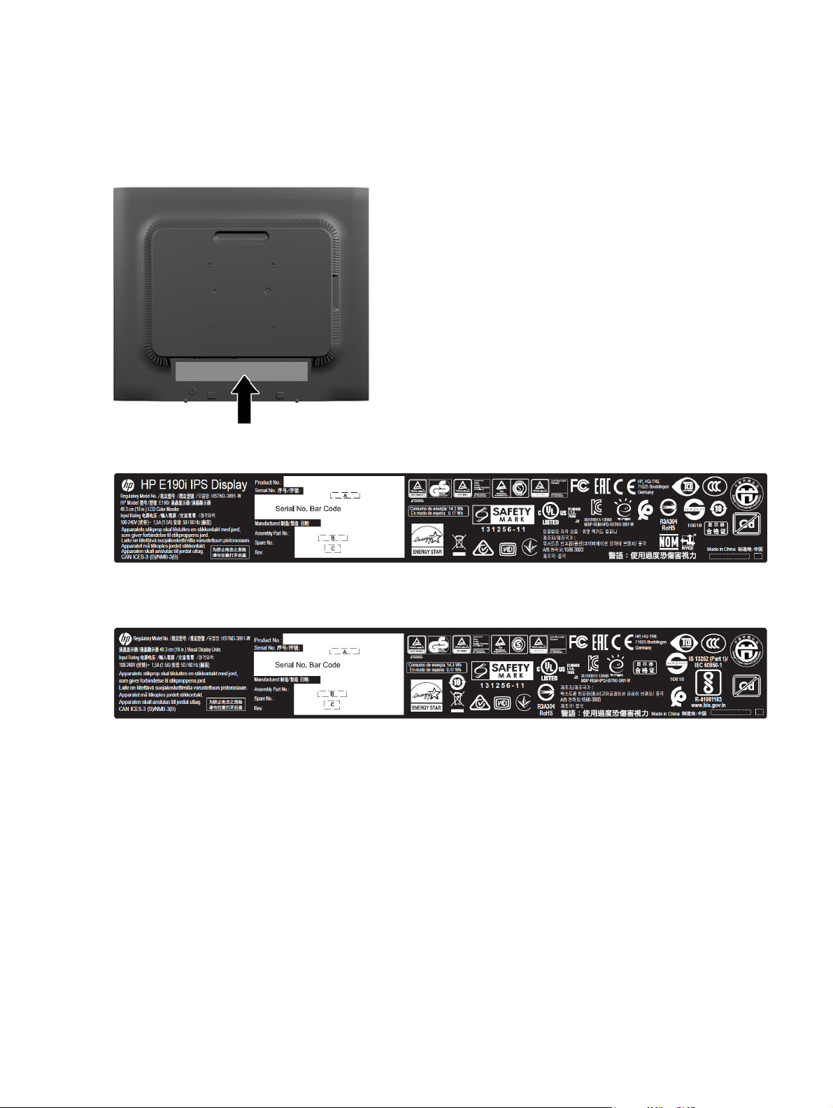
Locating the serial number and product number
The Spec and Barcode label are located on the rear of the monitor. The serial number and product number are
located on a Barcode label. You may need these numbers when contacting HP about the monitor model.
Barcode and Spec label (except India):
Barcode and Spec label (For India):
Autres manuels pour EliteDisplay E190i
1
Ce manuel convient aux modèles suivants
1
Table des matières
Autres manuels HP Moniteur


HP
HP LV1561W Manuel utilisateur

HP
HP P Class 733/800/866MHz / 1GHz Manuel

HP
HP Compaq LA2405wg Manuel utilisateur

HP
HP Pavilion W2558HC Manuel utilisateur

HP
HP LD5511 Instructions d'installation

HP
HP Z27i Manuel utilisateur

HP
HP L1910 Manuel utilisateur

HP
HP FS7600 Series Manuel utilisateur

HP
HP D8911 Manuel utilisateur

HP
HP L2401x Manuel utilisateur


