Horizon International BQ-P6 Manuel utilisateur


SERVICE MANUAL
Kyoto,Japan
510 Kuze Ooyabu-cho Minami-ku, Kyoto 601-8206, Japan
Phone:+81-75-934-6700, Fax:+81-75-934-6708, URL http://www.horizon.co.jp/
BQ-P6 Perfect Binder

IUS502007-04060905/BQP6/04E/DV
FOREWORD
Perfect Binder
Model BQ-P6
Do not perform any maintenance until you read and
understand the instructions in this manual.
If you have questions regarding maintenance or this publication,
please contact our service division.
This manual is designed to help you to keep the machine in a good operating
condition. Read, study and keep this manual in a safe and convenient place.
The machine design and specifications are subject to
change without notice.
II
Safety Instruction
1. Read and understand all safety instructions with a signal WARNING,
and CAUTION. If safety instructions are ignored, personal injury will
result.
2. HORIZON INTERNATIONAL INC. cannot anticipate every possible situa-
tion that might involve a potential hazard. The instruction in this manual are
therefore not all inclusive.
3. Be sure to unplug the power cord when replacing the parts or repairing the
machine.
4. Take care with the rotating parts when the machine is operated with the covers
being opened.
5. Use the original HORIZON spare parts when replacing the parts.

III
I Necessary Tool for Maintenance and Repair
Use the following tools for maintenance and repair.
1. Screw Driver No. 2
2. Screw Driver 6 to 7 mm
3. Allen Wrenches 1.5, 2, 2.5, 3, 4, 5, and 6 mm
4. Open-ended Wrench 5.5 x 7 mm 8 x 10 13 x 17
5. Box Wrench 5.5 mm
6. Snap-ring Expander
II Signs and Abbreviations in This Manual
1. The following signs in this manual
represent wire color.
Sign Color
C Brown
RRed
O Orange
Y Yellow
G Green
B Blue
V Violet
H Gray
W White
D Black
S Transparent
DH Dark Gray
2. The following abbreviations in this manual
represent electronic and electrical parts.
Abbreviation Meaning
CL Clutch
BK Brake
SW Switch
mSW Microswitch
M Motor
LED Light Emitted Diode
VR Potentiometer
RY Relay

IV
Contents
FOREWORD .......................................................................................................................... I
Safety Instruction ................................................................................................................... II
I Necessary Tool for Maintenance and Repair ................................................................... III
II Signs and Abbreviations in this manual ........................................................................... III
1. Specifications ................................................................................................................... 1
2. Operation Procedure ...................................................................................................... 2
3. Leveling Adjustment for Glue Application ................................................................... 4
4. Drive Section Descriptions ............................................................................................. 5
5. How to Remove Cover .................................................................................................... 6
6. Troubleshooting ............................................................................................................... 7
7. Sensor and Electronic Parts Locations ......................................................................... 12
8. Switch Position Adjustment ........................................................................................... 13
9. Control P.C.B. LED Descriptions .................................................................................. 14
10. Electronic Circuit Diagram .......................................................................................... 15
11. Check Mode ................................................................................................................... 16
12. Melt Tank Replacement ............................................................................................... 17
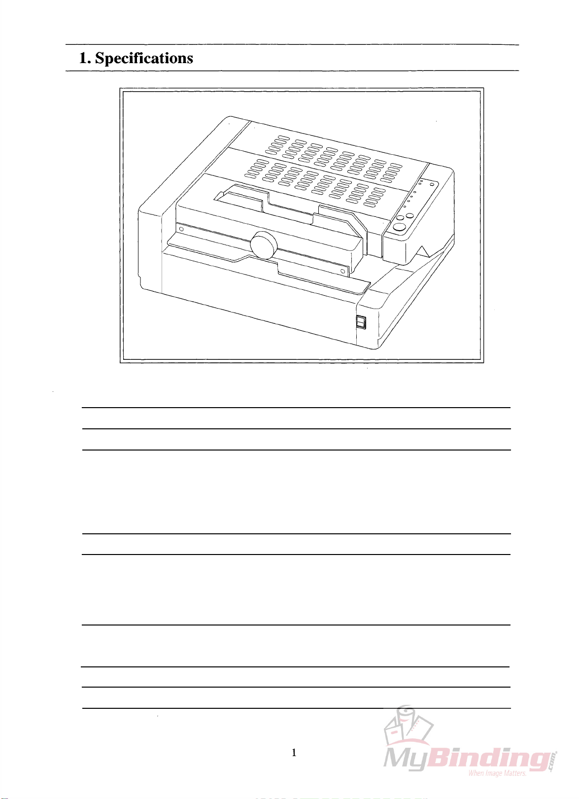
MaximumBookSize
MaximumBookThickness
BindingType
ProductionSpeed
WarmingUpTime
PowerConsumption
MachineDimentions
(WxDxH)
MachineWeight
MeltTankCapacity
UptoA4Size
25mm(1")
CoverBinding,TapeBindingandPadding
Cover/TapeBindingMode:30seconds/book(50Hz)
27seconds/book(60Hz)
PadBindingMode:36seconds/book(50Hz)
33seconds/book(60Hz)
13minutes
100V-50/60Hz1050W
115V-60Hz1050W
230V-50Hz1050W
560x460280mm
(22"x18"x11")
32kg(64.8lb)
350g

2
2. Operation Procedure
Cover/Tape Binding Mode
Turn on power switch.
About 13 minutes
later.
Set sheets into
clamper.
Press start button.
Set cover sheet or tape
and press start button
again.
Take out book.
Press reset button.
- Heater begins to warm up.
- "Preparation" lamp illumi-
nates.
- "Cover/Tape Mode" lamp
illuminates.
- Alarm sounds.
- "Preparation" lamp goes out.
- "Insert stock. Depress start
button." lamp illuminates.
- Nipper lowers and clamper
moves to the rear side and
stops above melt tank while
"Operation" lamp is illuminat-
ing.
- "Operation" lamp goes out.
- "Place cover sheet. Depress
start button." lamp illuminates.
- "Operation" lamp illuminates.
- Clamper goes back to home
position and stops on nipper.
- Nipper rises to nip cover
sheet and stock.
- Alarm sounds and nipper
lowers.
- "Operation" lamp goes out.
- "Take out stock. Depress
reset button." lamp illuminates.
- "Operation" lamp illuminates.
- Nipper rises.
- "Operation" lamp goes out.
- "Insert stock. Depress start
button." lamp illuminates.
Operation Sensor or SwitchAction (Operation Panel LED)
1
2
3
4
5
6
7
- Clamper home position switch
ON
- Nipper upper limit
microswitch OFF
- Sheet presence microswitch
ON
- Nipper lower limit
microswitch OFF
- Clamper reverse switch ON
- Cover sheet sensor ON
- Clamper home position switch
ON
- Nipper lower limit
microswitch OFF
- Stock presence microswitch
OFF
- Nipper upper limit
microswitch OFF

3
1
2
3
4
5
6
7
Turn on power switch.
About 13 minutes
later.
Select binding mode.
Set sheets into
clamper.
Press start button.
Take out book.
Press reset button.
- Heater begins to warm up.
- "Preparation" lamp illumi-
nates.
- "Cover/Tape Mode" lamp
illuminates.
- Alarm sounds.
- "Preparation" lamp goes out.
- "Insert stock. Depress start
button." lamp illuminates.
- Lamp moves from "Cover/
Tape Mode" to "Padding
Mode".
- Nipper lowers and clamper
moves to the rear side and
stops above melt tank while
"Operation" lamp is illuminat-
ing.
- Alarm sounds
- "Operation" lamp goes out.
- "Take out stock. Depress
reset button." lamp illuminates.
- "Operation" lamp illuminates.
- Nipper rises.
- "Operation" lamp goes out.
- "Insert stock. Depress start
button." lamp illuminates.
Operation Sensor or Switch
Action (Operation Panel LED)
- Clamper home position switch
ON
- Nipper upper limit
microswitch OFF
- Sheet presence microswitch
ON
- Nipper lower limit
microswitch OFF
- Clamper switch temporarily
ON
- Clamper home position switch
ON
- Stock presence microswitch
OFF
- Nipper upper limit
microswitch OFF
2. Operation Procedure
Padding Mode
4
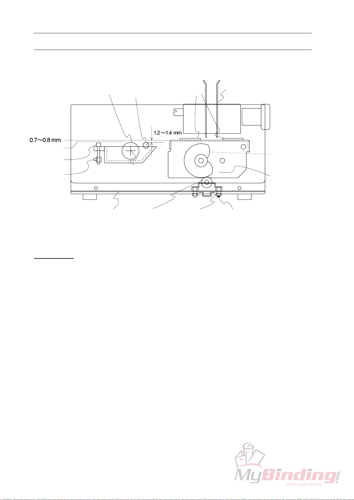
Clamper
Operation Side
Lock Bolt (Black)
Lock Bolt (Yellow)
Bottom Plate
Lock Screw
Scrape Roller
Adjust Bolt
Level 0
Application Drum
Pivot
Bearing
Scrape Roller Nippers
Cam
(While stock is set.)
Nipper Base
3. Leveling Adjustment for Glue Application
Construction
Each section is adjusted based on the upper surface of application drum as the pivot of appli-
cation drum is fixed to the standard position.
1. Nipper Base Adjustment during Nipping Stocks
- Adjust nipper base with adjust bolt (Yellow) on the bottom of melt tank.
NOTE
- The clearance between the upper surface of application drum and the upper surface of
nipper must be 0.7 ~ 0.8 mm.
- Be sure to loose lock bolt (Black) before adjustment and fasten lock bolt (Black) after
adjustment.
2. Scrape Roller Adjustment
- Adjust scrape roller with scrape roller adjust bolt on melt tank.
NOTE
- It is easier to adjust scrape roller based on the upper surface of nipper which is adjusted
before.
- The clearance between the upper surface of scrape roller and the upper surface of nipper
must be 1.2 ~ 1.4 mm.
- Be sure to loose lock screw before adjustment and fasten lock screw after adjustment.
- Nipper base is lowered by cam while stock is nipped.
Table des matières


