Hettich HettCube 200 Manuel utilisateur

200/200 R; 400/400 R; 600/600 R
Read the instructions prior to performing any task!
Translation of the original operating manual
HettCube
Operating manual
1 / 173
en
12.2020 / Rev. 01
AB66006

en
12.2020 / Rev. 01
AB66006
2 / 173
Andreas Hettich GmbH & Co. KG
Föhrenstraße 12
D-78532 Tuttlingen/Germany
+49 (0)7461/705-0
+49 (0)7461/705-1125
www.hettichlab.com
© 2019

3 / 173
en
12.2020 / Rev. 01
AB66006
Table of contents
Table of contents
1 Introduction. . . . . . . . . . . . . . . . . . . . . . . . . . . . . . . . . . . . . . 7
1.1 Symbols. . . . . . . . . . . . . . . . . . . . . . . . . . . . . . . . . . . 7
1.2 Symbol on the shipping carton label. . . . . . . . . . . . . 10
1.3 Personal protective equipment. . . . . . . . . . . . . . . . . 11
1.4 Personnel qualication. . . . . . . . . . . . . . . . . . . . . . . 11
1.5 Intended use. . . . . . . . . . . . . . . . . . . . . . . . . . . . . . 12
1.6 Replacement parts/consumable material. . . . . . . . . 13
1.7 Scope of delivery. . . . . . . . . . . . . . . . . . . . . . . . . . . 13
1.8 Return shipments. . . . . . . . . . . . . . . . . . . . . . . . . . . 13
2 Safety information. . . . . . . . . . . . . . . . . . . . . . . . . . . . . . . . . 14
3 Device description. . . . . . . . . . . . . . . . . . . . . . . . . . . . . . . . 16
3.1 Standard device. . . . . . . . . . . . . . . . . . . . . . . . . . . . 16
3.2 Options. . . . . . . . . . . . . . . . . . . . . . . . . . . . . . . . . . 18
3.2.1 Glass door. . . . . . . . . . . . . . . . . . . . . . . . . . . . . . . 18
3.2.2 Additional device access port. . . . . . . . . . . . . . . . . 19
3.2.3 Independent Pt100 temperature sensor with 4-20 mA
analogue output. . . . . . . . . . . . . . . . . . . . . . . . . . . 20
3.2.4 Switchboard. . . . . . . . . . . . . . . . . . . . . . . . . . . . . . 20
3.2.5 Continuous cooling (option). . . . . . . . . . . . . . . . . . 20
3.2.6 Passive dehumidication. . . . . . . . . . . . . . . . . . . . 21
3.3 Accessories. . . . . . . . . . . . . . . . . . . . . . . . . . . . . . . 21
4 Transport and storage. . . . . . . . . . . . . . . . . . . . . . . . . . . . . 24
5 Commissioning. . . . . . . . . . . . . . . . . . . . . . . . . . . . . . . . . . . 27
5.1 Unpacking the incubator. . . . . . . . . . . . . . . . . . . . . 27
5.2 Setting up, connecting and switching on the incubator
. . . . . . . . . . . . . . . . . . . . . . . . . . . . . . . . . . . . . . . . . 30
5.2.1 Installing the incubator. . . . . . . . . . . . . . . . . . . . . . 30
5.2.2 Incubator connection. . . . . . . . . . . . . . . . . . . . . . . 31
5.2.3 Initial commissioning. . . . . . . . . . . . . . . . . . . . . . . 35
5.3 Inserting and removing the slide-in modules. . . . . . . 38
5.3.1 Standard slide-in modules. . . . . . . . . . . . . . . . . . . 38
5.3.2 Telescopic slide-in modules. . . . . . . . . . . . . . . . . . 39
6 Operation. . . . . . . . . . . . . . . . . . . . . . . . . . . . . . . . . . . . . . . 41
6.1 Operating elements. . . . . . . . . . . . . . . . . . . . . . . . . 43
6.2 Loading. . . . . . . . . . . . . . . . . . . . . . . . . . . . . . . . . . 43
6.3 Door locking mechanism. . . . . . . . . . . . . . . . . . . . . 44
6.4 Fixing the mechanical display protection of the control
panel. . . . . . . . . . . . . . . . . . . . . . . . . . . . . . . . . . . . 45
6.5 Standard check before every use. . . . . . . . . . . . . . . 45

en
12.2020 / Rev. 01
AB66006
4 / 173
Table of contents
6.6 Switching on the incubator. . . . . . . . . . . . . . . . . . . . 46
6.7 Initialization. . . . . . . . . . . . . . . . . . . . . . . . . . . . . . . . 46
6.8 Operating modes. . . . . . . . . . . . . . . . . . . . . . . . . . . 47
6.8.1 Functional description of standstill mode. . . . . . . . 47
6.8.2 Functional description of manual mode. . . . . . . . . 48
6.8.3 Functional description of program mode. . . . . . . . 49
6.9 Main screen. . . . . . . . . . . . . . . . . . . . . . . . . . . . . . . 50
6.10 Process ow information. . . . . . . . . . . . . . . . . . . . . 52
6.11 Manual mode. . . . . . . . . . . . . . . . . . . . . . . . . . . . . . 54
6.11.1 Manual mode settings. . . . . . . . . . . . . . . . . . . . . . 54
6.11.2 Starting manual mode. . . . . . . . . . . . . . . . . . . . . . 66
6.11.3 Manual mode changes during running operation. . 67
6.12 Program mode. . . . . . . . . . . . . . . . . . . . . . . . . . . . . 69
6.12.1 Program mode settings. . . . . . . . . . . . . . . . . . . . . 69
6.12.2 Creating a program. . . . . . . . . . . . . . . . . . . . . . . . 70
6.12.3 Editing a program. . . . . . . . . . . . . . . . . . . . . . . . . . 78
6.12.4 Copying and deleting a program. . . . . . . . . . . . . . 81
6.12.5 Program mode — Start settings. . . . . . . . . . . . . . . 84
6.12.6 Program mode overview. . . . . . . . . . . . . . . . . . . . 90
6.13 Device settings. . . . . . . . . . . . . . . . . . . . . . . . . . . . . 93
6.13.1 About. . . . . . . . . . . . . . . . . . . . . . . . . . . . . . . . . . . 95
6.13.2 Date & time. . . . . . . . . . . . . . . . . . . . . . . . . . . . . . 95
6.13.3 Temperature. . . . . . . . . . . . . . . . . . . . . . . . . . . . . . 96
6.13.4 Tolerance band. . . . . . . . . . . . . . . . . . . . . . . . . . . . 97
6.13.5 Temperature guard. . . . . . . . . . . . . . . . . . . . . . . . . 98
6.13.6 Control contact (option). . . . . . . . . . . . . . . . . . . . 101
6.13.7 Language. . . . . . . . . . . . . . . . . . . . . . . . . . . . . . . 105
6.13.8 Sound. . . . . . . . . . . . . . . . . . . . . . . . . . . . . . . . . 105
6.13.9 Door. . . . . . . . . . . . . . . . . . . . . . . . . . . . . . . . . . . 106
6.13.10 Screen. . . . . . . . . . . . . . . . . . . . . . . . . . . . . . . . . 106
6.13.11 Power failure. . . . . . . . . . . . . . . . . . . . . . . . . . . . 108
6.13.12 Failure alarm. . . . . . . . . . . . . . . . . . . . . . . . . . . . . 109
6.13.13 Export. . . . . . . . . . . . . . . . . . . . . . . . . . . . . . . . . 109
6.13.14 Import. . . . . . . . . . . . . . . . . . . . . . . . . . . . . . . . . 112
6.13.15 Hours of operation. . . . . . . . . . . . . . . . . . . . . . . . 114
6.13.16 Logbook. . . . . . . . . . . . . . . . . . . . . . . . . . . . . . . 114
6.13.17 System information. . . . . . . . . . . . . . . . . . . . . . . 115

5 / 173
en
12.2020 / Rev. 01
AB66006
Table of contents
6.13.18 Admin access. . . . . . . . . . . . . . . . . . . . . . . . . . . 115
6.13.19 Service dashboard. . . . . . . . . . . . . . . . . . . . . . . . 118
6.14 Heat compensation. . . . . . . . . . . . . . . . . . . . . . . . 118
7 Cleaning, disinfection and maintenance. . . . . . . . . . . . . . . 120
7.1 Cleaning. . . . . . . . . . . . . . . . . . . . . . . . . . . . . . . . . 121
7.2 Disinfection. . . . . . . . . . . . . . . . . . . . . . . . . . . . . . . 123
7.3 Removal of radioactive contaminants. . . . . . . . . . . 123
7.4 Autoclaving. . . . . . . . . . . . . . . . . . . . . . . . . . . . . . 124
7.5 Maintenance. . . . . . . . . . . . . . . . . . . . . . . . . . . . . 124
8 Troubleshooting. . . . . . . . . . . . . . . . . . . . . . . . . . . . . . . . . 125
8.1 Activating the automatic circuit breaker. . . . . . . . . 125
8.2 Warnings and error messages. . . . . . . . . . . . . . . . 126
8.2.1 Door warning. . . . . . . . . . . . . . . . . . . . . . . . . . . . 131
8.2.2 Event overview. . . . . . . . . . . . . . . . . . . . . . . . . . . 132
8.2.3 Tolerance band alarm. . . . . . . . . . . . . . . . . . . . . . 132
8.2.4 Temperature protection, class 3.1 / 3.2. . . . . . . . 132
9 Technical data. . . . . . . . . . . . . . . . . . . . . . . . . . . . . . . . . . 133
9.1 HettCube 200. . . . . . . . . . . . . . . . . . . . . . . . . . . . 133
9.2 HettCube 200 R. . . . . . . . . . . . . . . . . . . . . . . . . . . 134
9.3 HettCube 400. . . . . . . . . . . . . . . . . . . . . . . . . . . . 136
9.4 HettCube 400 R. . . . . . . . . . . . . . . . . . . . . . . . . . . 137
9.5 HettCube 600. . . . . . . . . . . . . . . . . . . . . . . . . . . . 139
9.6 HettCube 600 R. . . . . . . . . . . . . . . . . . . . . . . . . . . 141
9.7 Denition of the utilized space. . . . . . . . . . . . . . . . 143
9.8 Type plate. . . . . . . . . . . . . . . . . . . . . . . . . . . . . . . . 144
9.9 Dimensions. . . . . . . . . . . . . . . . . . . . . . . . . . . . . . 145
10 Disposal. . . . . . . . . . . . . . . . . . . . . . . . . . . . . . . . . . . . . . . 147
11 Free and Open Source Software. . . . . . . . . . . . . . . . . . . . . 148
12 Index. . . . . . . . . . . . . . . . . . . . . . . . . . . . . . . . . . . . . . . . . 149
13 Appendix. . . . . . . . . . . . . . . . . . . . . . . . . . . . . . . . . . . . . . 153
A Software symbols. . . . . . . . . . . . . . . . . . . . . . . . . . 155
B Examples. . . . . . . . . . . . . . . . . . . . . . . . . . . . . . . . 159
B.1 Temperature drop during the entire weekend (Friday
afternoon to Monday morning). . . . . . . . . . . . . . . 159
B.2 Temperature drop over one day (Sunday). . . . . . . 160
B.3 Temperature drop with holiday function (using Wed-
nesday as an example). . . . . . . . . . . . . . . . . . . . . 160
B.4 Temperature drop on the weekend with start delay161
B.5 Temperature drop on the weekend including the pas-
sive dehumidication option. . . . . . . . . . . . . . . . . 162

en
12.2020 / Rev. 01
AB66006
6 / 173
Table of contents
B.6 External devices are integrated in program mode, e.g.
DAY/NIGHT simulation.. . . . . . . . . . . . . . . . . . . . 163
B.7 Combination of standstill mode with incubation mode
(energy-saving mode). . . . . . . . . . . . . . . . . . . . . . 164
B.8 Incubator is always cleaned on Wednesdays due to
the laboratory routine (SOP) (standstill mode). . . . 165
C Accessory overview. . . . . . . . . . . . . . . . . . . . . . . . 167
D Declaration of conformity. . . . . . . . . . . . . . . . . . . . 171
E List of standards. . . . . . . . . . . . . . . . . . . . . . . . . . . 173
7 / 173
en
12.2020 / Rev. 01
AB66006
Introduction
Signal words
Warning categories
General symbols
1 Introduction
1.1 Symbols
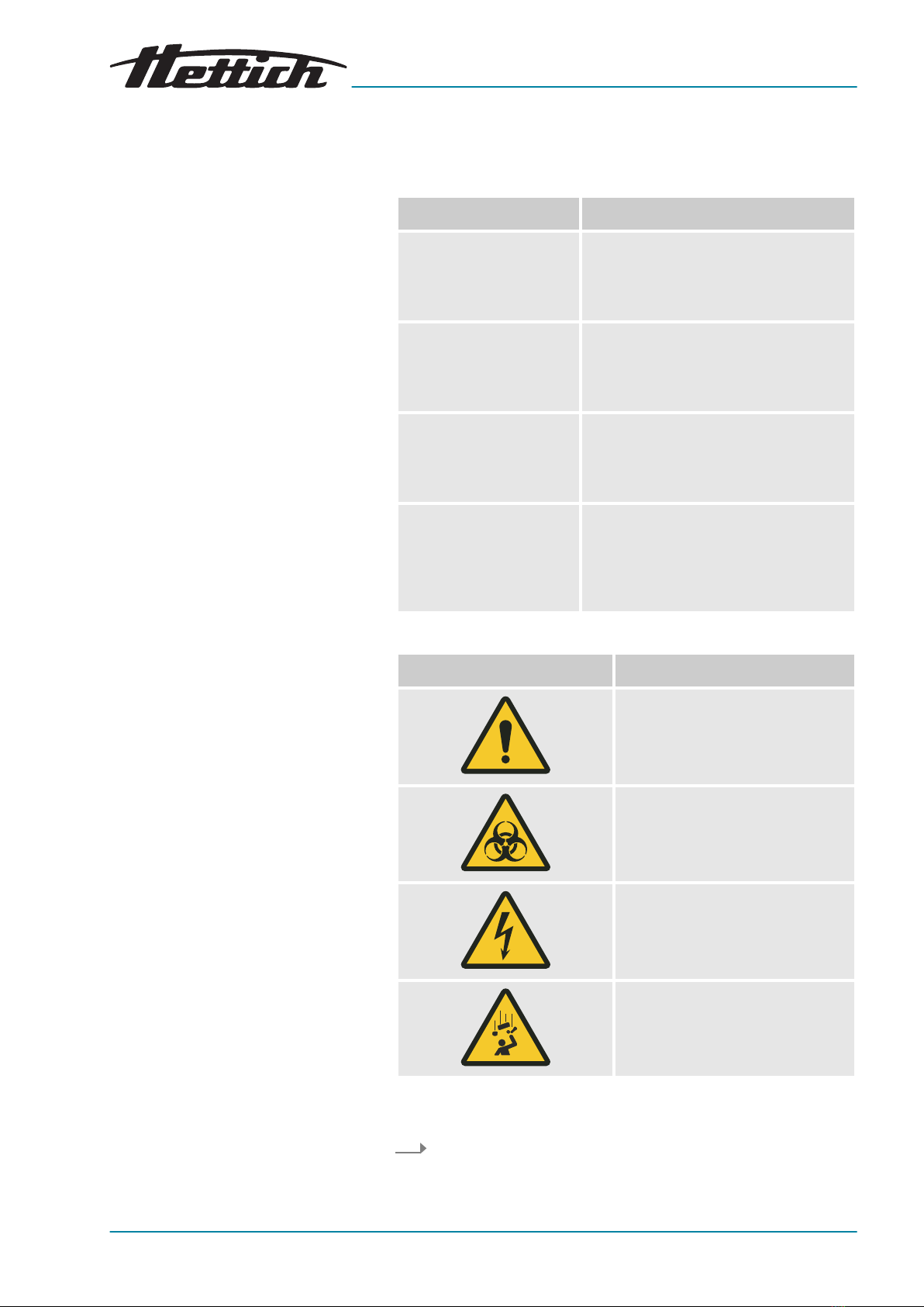
Signal word Meaning
DANGER This combination of symbol and signal
word indicates an immediate dan-
gerous situation that will result in death
or serious injury if it is not avoided.
WARNING This combination of symbol and signal
word indicates a possible dangerous
situation that can result in death or
serious injury if it is not avoided.
CAUTION This combination of symbol and signal
word indicates a possible dangerous
situation that can result in minor injury
if it is not avoided.
NOTICE This combination of symbol and signal
word indicates a possible dangerous
situation that can result in material and
environmental damage if it is not
avoided.
Warning signs Type of danger
Warning – danger zone.
Warning – biological hazard.
Warning – high-voltage.
Warning – falling objects.
This listing symbol denotes descriptions of tasks that you must
perform.
■This dot is for denoting lists.

en
12.2020 / Rev. 01
AB66006
8 / 173
Introduction
Symbols on the incubator
Cross references are indicated as follows:
Chapter 1.1 ‘Symbols’
on page 7
Warnings/symbols on the incubator which are no
longer recognizable should be immediately replaced
by the operating company.
The images shown in the following depict the posi-
tions of the warnings and symbols afxed to the
incubator.
Fig. 1: Information on the front side of the incubator, NON-IvD logo
NOT FOR IvD-USE
The device does NOT meet the requirements of the directive con-
cerning in-vitro diagnostics, 98/79/EC. Please observe the intended
use in this regard
Chapter 1.5 ‘Intended use’ on page 12
.
For IvD applications, Hettich offers IvD-compliant incubators.
Fig. 2: Information on the front side of the incubator

9 / 173
en
12.2020 / Rev. 01
AB66006
Introduction
Attention, general danger point
Nonobservance of this warning can lead to material damage and
personal injury.
Before using the incubator, make sure you read the operating
instructions and observe the safety information.
Attention: Biohazard
Nonobservance of this warning can lead to personal injury.
Before using the incubator, make sure you read the operating
instructions and observe the safety information.
Service information
The service information contains the data you will require when you
talk to the Service Hotline. This includes the order number, serial
number and year of construction.
Passive dehumidication 60042 inside (option)
The device is equipped with the passive dehumidifcation option.
Fig. 3: Information on the rear side of the incubator
Symbol for additional devices (for Switchboard option only)
This symbol indicates the maximum load for the connections of the
additional devices (for Switchboard option only).
Attention, general danger point
Nonobservance of this warning can lead to material damage and
personal injury.
Before using the incubator, make sure you read the operating
instructions and observe the safety information.
Symbol for separate collection of electric and electronic devices
Symbol according to directive 2002/96/EC (WEEE). Applies in the
countries of the European Union, as well as in Norway and Switzer-
land.

en
12.2020 / Rev. 01
AB66006
10 / 173
Introduction
Symbol for potential-free alarm output
This symbol indicates the potential-free alarm output.
Symbol for fuse (for Switchboard option only)
This symbol indicates the fuse 6F1 (for Switchboard option only).
Symbol for analogue output for independent temperature measure-
ment (option)
This symbol indicates the 4-20 mA analogue output for an inde-
pendent temperature measurement.
Symbol for analogue output for independent temperature measure-
ment (option)
This symbol indicates the 4-conductor analogue output for an inde-
pendent temperature measurement.
Symbol for TÜV-inspected device
The device safety requirements are inspected by TÜV (Technischer
Überwachungsverein, Engl: Technical Control Board).
Type plate
Nameplate with technical data specications.
Voltage variants
This sign supplements the nameplate and indicates the mains
voltage and mains frequency of the device, assuming they are dif-
ferent from the 220-240 V variant.
Passive dehumidication 60042 inside (option)
The device is equipped with the passive dehumidifcation option.
1.2 Symbol on the shipping carton label
This way up.
Shows the correct upright position of the package.
Autres manuels pour HettCube 200
1
Ce manuel convient aux modèles suivants
5
Table des matières


