HER CHEE ATV-50 Manuel utilisateur

SERVICE MANUAL
ATV-50/90/100 Ⅴ
October, 2002
High Power Engine
HER CHEE INDUSTRIAL CO., LTD.

Foreword
This service manual contains information on servicingATV-50/90/100.
This manual is written for use as a guideline only. It is recommended that any
mechanic, with or without sufficient experience, thoroughly read through the
manual and only attempt to service those areas that are fully understood in
accordance with the guidelines provided by this manual. For fully qualified
mechanics, this manual supplies service data necessary for repairs and
maintenance. It is highly recommended that a qualified mechanic, regardless of
technical level, should study the service manual in full before attempting service
on ATV-50/90/100.
All the data and diagrams provided in this service manual are valid at the time of
publication. Information may be updated without notice due to improvements or
upgrades.
No quotation, reproduction, or reprint of the service manual, as a whole or in part,
will be permitted without the express written consent from JEHM Motorsports.

I N D E X
Initial Set-Up Information-------------------------------------------------1
Information for Preparation-----------------------------------------------2
Check and Adjust----------------------------------------------------------3
Engine-
Lubrication System---------------------------------------------------------4
Fuel System-----------------------------------------------------------------5
Remove of Engine----------------------------------------------------------6
Cylinder Head / Cylinder / Piston----------------------------------------7
Starter / Driving Disc / Clutch / Transmission Disc--------------------8
Final Transmission Mechanism-------------------------------------------9
Crank case / Crank shaft--------------------------------------------------10
Chassis-
Front wheel, Brake, Suspension------------------------------------------11
Rear heel, Brake, Suspension --------------------------------------------12
Electrical devices-----------------------------------------------------------13
Wiring diagram-------------------------------------------------------------14

1-1
Initial Set-Up Information
Injector Oil
Use a good grade of oil that is specially formulated for two-stroke engines, synthetic type is
recommended. JEHM recommends SAE 30.
Transmission Gear Oil
Use multi-grade motor oil of SAE 90 or 85W-140.
Break-In Procedure
To insure maximum durability and optimal performance and to avoid engine damage, please
pre-mix the first four tanks of fuel with two-stroke engine oil at 30:1 ratio. Do not operate
the ATV at more than half throttle for the first three hours. During the break-in period (the
first four tanks of fuel), operate the vehicle at various RPM’s and do not operate the vehicle
above half throttle for extended periods.
Engine
The ATV-50/90/100 have a two-stroke, reed induction, piston port motor. It requires the use
of two-cycle oil and should never be run without oil in the oil tank. Extreme damage to the
motor will result.
Ignition System
The ignition system installed on ATV-50/90/100 is the Computerize Digital Ignition (CDI)
type. There is no maintenance required for this type of system.
Chassis
The chassis is constructed of mild steel tubing. If any frame repairs are necessary,
oxyacetylene welding can be used. If wire feed or arc welding is used, use extreme care and
disconnect the battery while welding.

1-2
Set-Up Procedure
The following instructions provided a general overview of the procedures needed to properly
set-up and deliver the ATV-50/90/100 to the retail customer.
1. Take out the battery and fill with acid liquid. Pre-charging the battery will extend its life.
The preparation and charge procedure is based on the battery’s instruction.
2. Install the rear wheels and parts in the following order:
A. 14x40x4.5mm washer (big)
B. 14x26x3mm washer (small)
C. 14mm hex-bolt (torque 450-550kg-cm, 44-54N-m)
D. Cotter pin (open up the end after installed)
E. Rubber cap
3. Install the front wheels and parts in the following order:
A. 13x21x4mm washer (small)
B. 12x40x4.5mm washer (big)
C. 12mm hex-bolt (torque 300-350kg-cm, 29.5-34N-m)
D. Cotter pin (open up the end after installed)
E. Rubber cap
4. Set the handle bar into the lock-pin of the steering base. Tie-up the 4 hex-socket bolts.
Install the rear cover into handle bar and adjust the cables and wires properly. Install the
front cover into the rear cover.
5. Pull the seat-lock cable and remove the seat. Install the battery with the red wire to
positive (+) and the black wire to the negative (-).
6. Remove the oil tank cap and fill with 2 stroke oil (SAE 30)of a synthetic and low-smoke
type, and enough unleaded gasoline to operate. Be sure the arrow mark on the fuel valve
arm (petcock) is set into the correct position (on).
7. Install the Front Bumper.
8. Turn on the main switch and try to start up the engine. In order to use the electric starter,
you need to check the following.
A. Turn on the engine operation switch located on left handle bar
B. Pull the rear-brake lever
C. Push the electric starter bottom to left or right
9. If the vehicle is operating in a very dusty area, please add more oil on the air cleaner filter.

1-3
PDI (PRE DELIVERY INSPECTION)
(For ATV-50/90/100)
□ 1. Record the frame and engine number into the owner’s manual.
□ 2. Check that all tires have correct pressure specified on the tire or in the owner’s manual.
□ 3. Engine lubrication oil (2 stroke, Grade SAE30) tank is filled.
□ 4. Battery is installed properly.
□ 5. All brake cables are adjusted properly.
□ 6. Fuel tank has enough gasoline to operate.
□7. Check the suspension and drive chain for proper setup.
□ 8. Check that all electrical components and lights are working properly.
□ 9. Make sure that the owner’s manual and tool bag are installed under the seat.
If there are any other questions, please check the owner’s manual for details.
CAUTION: Before install the front rim, beware the stopperof front brake plate assembly
must fit into the front knuckle 7-mm plate.

2-1
INFORMATION FOR PREPARATION
Attention on Operation
zAll washers, oil rings, clamp rings, opening pins shall be duly replaced by a new item
when dismounted.
zLocking of all screws, nuts, cross screws shall be performed in the order of first the
large screws and then the small ones and from inside to outside in opposite angles by
tightening the torque locks.
zAll items must use original parts, pure oil and greases.
zAll service shall use special tools and general tools to repair.
zAll dismounted items requiring for checks shall be duly cleaned and for assembly, all
items shall be duly lubricated.
2-2
INFORMATION FOR PREPARATION
Attention on Operation
zCertified lubricants in cans shall be used on all the elements to be lubricated.
zAfter assembly, performance of all elements shall be duly checked and the locking shall
be duly verified.
zIn case of an operation is performed by over 2 people, the assignment shall be
conducted in coordination and safety shall be the first priority.
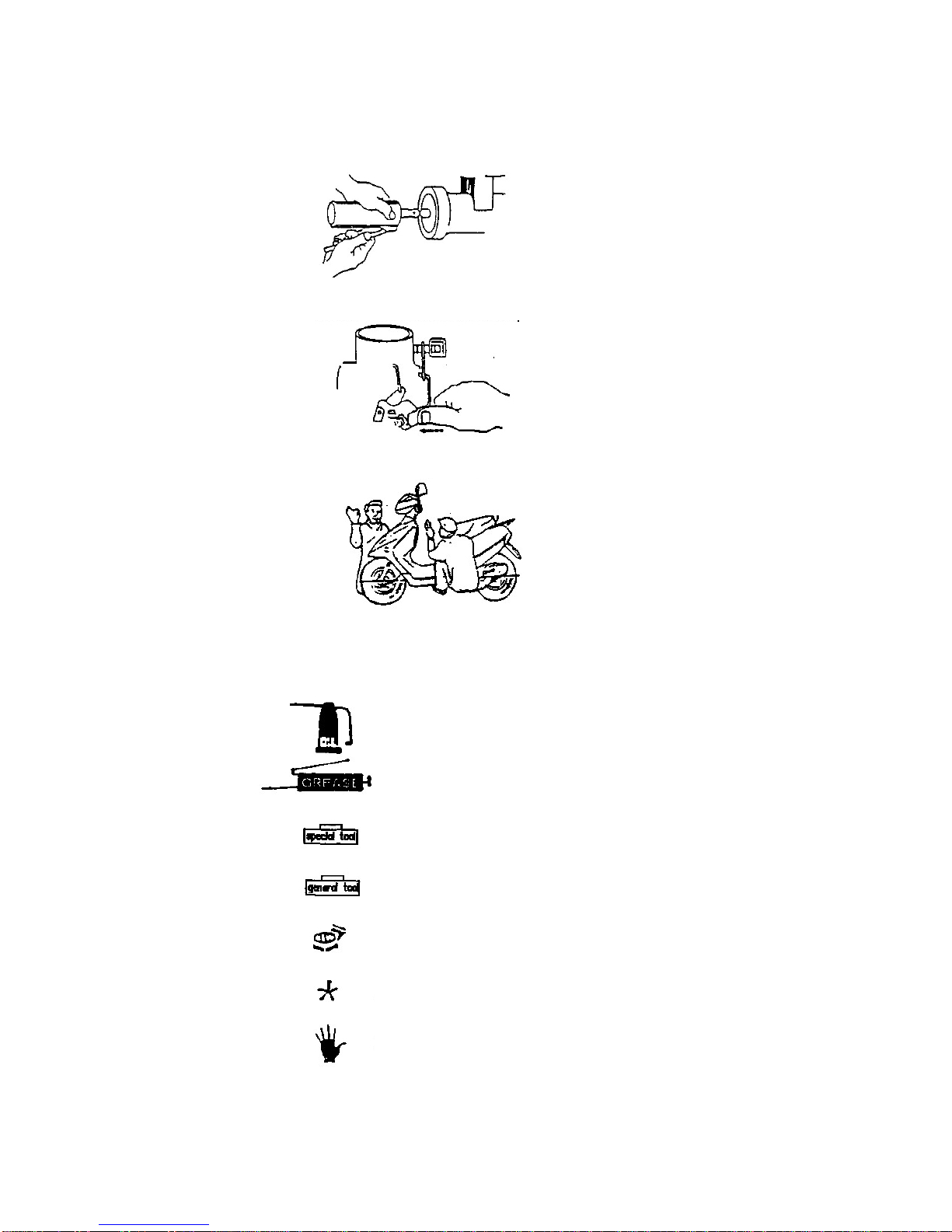
zDefinition of signs:
The sign given in the Service Manual shall refer to the operation methods and
observation.
OIL: Lubrication by designated lubricant.
GREASE: Lubrication by grease
Special Tool: Parts on which special tools shall be used
Tool: General tools shall be used
New: Replace by new items after dismounting
Attention
Dangerous and important operations

2-2
INFORMATION FOR PREPARATION
SPECIFICATION
MODEL ATV-50 ATV-90 ATV-100
ENGINE 50 C.C. 90 C.C. 100 C.C.
TYPE AIR-COOLED, 2-STROKE SINGLE CYLINDER
STARTING KICK & ELECTRIC
LUBRICATION OIL PUMP SEPARATE SUPPLY
TRANSMISSION AUTOMATIC (C.V.T. V-BELT)
SPARK PLUG NGK BP7HS
BATTERY 12V-4AH (Maintenance-free)
OIL CAPACITY 1.0 Liter
FUEL TANK 5.0 Liter
OVERALL LENGTH 1465mm 1525mm
OVERALL WIDTH 875mm 890mm
OVERALL HEIGHT 890mm 930mm
SEAT HEIGHT 700mm 740mm
WHEEL BASE 955mm
CLAIMED DRY WEIGHT 103KG 108KG
FRONT BRAKE DOUBLE DRUM
REAR BRAKE DRUM
FRONT SUSPENSION OIL DAMPED, INDEPENDENT, SINGLE A-ARM
REAR SUSPENSION OIL DAMPED, SWING SINGLE SHOCK
FRONT TIRE 19*7-8(16*8-7)20*7-8
REAR TIRE 19*7-8(16*8-7)18*9.5-8
☆SPECIFICATIONS SUBJECT TO CHANGE WITHOUT ANY NOTICE. ☆

2-4
INFORMATION FOR PREPARATION
LOCKING TORQUE
Adopt the standard torque locking for the item unlisted.
STANDARD TORQUE:
Type Locking Torque (kg-m)
5 mm Screw 0.4
6 mm Screw 1.0
6 mm Hex Washer Face Bolt / Nut 1.2
8 mm Hex Washer Face Bolt / Nut 2.7
10 mm Hex Washer Face Bolt / Nut 4.0
CHASSIS:
Locking Place Quantity Dia. (mm) Locking Torque (kg-m)
Front Wheel Axle Nut 1 12 3.5
Rear Axle Nut 1 14 5.0
Rear Brake Arm Screw 1 6 1.2
Front Shock Absorber 4 10 4.0
Rear Shock Absorber 2 10 4.0
Engine Mounting Nut – Front 1 10 4.5
Engine Mounting Nut – Rear 1 8 3.0
ENGINE:
Locking Place Quantity Dia. (mm) Locking Torque (kg-m)
Screw of Cylinder Cap 4 6 1.0
Flywheel Nut 1 10 3.8
Clutch Cover Nut 1 10 3.8
Clutch Carrier Nut 1 28 5.5
Nut of Primary Fix Sheave 1 10 3.8
Oil-check Screw 1 8 1.3
Joint Screw of Exhaust Muffler 2 6 1.2
Exhaust Pipe Support Screw of Muffler 1 8 3.0
Spark Plug 1 14 1.4
Bolt of Crank Shaft Case 6 6 1.0
Ce manuel convient aux modèles suivants
4
Table des matières
Autres manuels HER CHEE Véhicule tout-terrain


