helivol Interceptor 400 Manuel utilisateur

PLEASE READ THROUGH THIS INSTRUCTION
MANUAL CAREFULLY. IT CONTAINS IMPOR-
TANT INSTRUCTIONS AND WARNINGS CON-
CERNING THE ASSEMBLY AND USE OF THIS
MODEL.
www.helivol.com
Specications:
Length: 630mm
Height: 225mm
Main Rotor: 558mm
Tail Rotor: 150mm
Weight: 300g
Flying Weight 580-620g
Motor Gear: Variable
Main Gear: 138T
Hold Rotation Gear: 105T
Tail Gear: 1:9.85:5
INSTRUCTION MANUAL
www.helivol.com

2
IntroductIon..................................2
EssEntIal EquIpmEnt.....................3
BuIld GuIdE..................................5-12
opEratIonal procEdurEs...........13
parts lIst...................................13-14
rotor HEad dIaGram....................15
swasHplatE dIaGram...................16
FramE dIaGram..............................17
FramE assEmBly dIaGram...........18
taIl dIaGram..................................19
lInkaGEs dIaGrams.................20-21
warranty........................................23
The Interceptor 400 is an aerobatic capable
helicopter, offering the performance and y-
ing abilities of 30 - sized nitro helicopter but
within a smaller package.
This is not a toy helicopter. It features a
double-dampened head, belt-driven tail
rotor and aluminium frame. This is a real
helicopter that is more than ready to y any-
where that you can nd a safe landing.
Take care when assembling the Interceptor
400. Incorrectly aligned parts will restrict
the helicopter’s abilities when performing
the extreme aerobatics it has been de-
signed for.
For the latest technical updates or manual
corrections please visit the Helivol website
at www.helivol.com.
warnInG
Strict pre-ight inspections are mandatory
for real aircraft. Although the R/C helicopter
is small and can be own with relative ease,
it does not differ from real aircraft in that if it
were to hit a person or object it could cause
serious damage and/or injury.
If an accident were to occur during opera-
tion the pilot would be held responsible.
Therefore it is recommended that users
possess remote control insurance. Details
on different schemes are available from
your local model shop or online.
Always be sure to inspect the helicopter
before any ight for any signs of damage or
wear. If the helicopter is own in a degrad-
ed condition it is possible for a catastrophic
failure to result.
Immediately replace any part that appears
worn or damaged.
Helivol © Copyright 2009
MADE IN TAIWAN
www.helivol.com

3
Transmitter
Receiver and Servos (3 Collective, 1 Tail)
Gyro
Battery and Charger
Motor
Electronic Speed Controller
Tools:
Pitch Gauge Blade Balancer
Ball Link Pliers Cross Wrench
Allen Wrench
Philips Screwdriver
Box Drive 4mm
Equipment needed:

4
cHoosInG your EquIpmEnt:
The INTERCEPTOR 400 is an impressive
kit helicopter but it requires additional com-
ponents to be operational. You will need
four servos, a radio transmitter and receiver,
a gyro, ESC, motor and lipo battery. We
have carried out substantial tests on various
setups and congurations.
radIo EquIpmEnt
This helicopter requires at minimum a 6CH
transmitter and receiver. It must have the
ability to setup a mechanical mix function on
a 90 degree swashplate. However we rec-
ommend that your radio transmitter also has
the capacity to programme multiple throttle
and pitch curves.
sErVos
We have tested a wide range of servos for
this model. We recommend Acer-Lab A8-
SG. They are fast analogue servos that can
be used with an Alien command. They are
also a perfect t for the frame. Please note
that digital servos can not be used in con-
junction with the Alien Command.
Gyro
You can use any high quality heading hold
gyro with this helicopter. Check compatibil-
ity with your radio equipment.
BattEry
The INTERCEPTOR 400 requires a Lipo
with a capacity of between 1500-2200mAh
and a minimum discharge of 15C for basic
hovering. This helicopter runs on 11.1v (3
Cell’s). Flight time will be between 7-12 min-
utes depending on ight conditions.
The maximum size battery the INTERCEP-
TOR 400 can hold is:
Width: 32.5mm
Height: 28.0mm
Length 104.0mm
Anything larger than this will not t in the
frame and canopy! A well tted battery
makes ying much easier.
motor
We recommend a Acer-Lab Brushless Mo-
tor. This will deliver the power needed to
get the most from the INTERCEPTOR 400
but you can use any motor within the range
2800-3500kv with a suitable pinion.
Esc
We recommend the Acer-Lab 40A. It is
fully programmable and features a double
heatsink, plug and play functionality. It also
boasts a 2 year warranty against defects in
material and workmanship. Any other qual-
ity ESC will also work.
cHarGEr
The battery used for this helicopter will
require a charger for a 3 Cell (11.1V) lipo
battery.

5
Measure the ybar so that is it equal on
both sides of the head. Approx 60mm on
each side.
Thread lock the screws into place then
attach the paddles ensuring that they run
parallel with the head.
BuIld GuIdE:
The INTERCEPTOR 400 is a kit helicopter
this guide covers the INT-401 ARF. In this
section we will take you through the process
to ensure that you correctly assemble your
model. This is a general guide only we rec-
ommend consulting individual component
manuals to ensure correct conguration and
installation. For a complete and thorough
guide on assembly along with videos and
the latest tips and upgrades please visit -
www.helivol.com
assEmBlInG tHE FramE & HEad
The head for the INTERCEPTOR 400
comes assembled in the ARF kit. You need
will need to install the ybar and paddles.
Remove the retaining screw and insert the
ybar.

Place the washer onto the collar of the
main gear. Insert the main shaft through
the frame and into place.
Place the main gear into the frame and
push the shaft through - the washer should
be facing up. Once in place align the holes
in the gear and shaft and t the bolt and nut
use loctite to secure.
Please check that the collar on the main
shaft is secure and correctly holds the head
assembly in place.
skIds
Assemble skids - the uprights with the wider
attachments points are located at the front.
Screw the uprights into place and align the
skid tubes.
6

Align the hole on the end of the boom with
the plastic pin inside the tail rotor assembly.
It will clip into place and hold rm.
Slide the tail push rod holder on to the
boom. Check that the belt is not twisted.
Insert boom into frame aligning the lip with
the groove.
Boom
You will need to feed the belt through the
boom.
We recommend taping the tail push rod to
the belt and then dropping it through the
boom before drawing through the belt after
it.
7
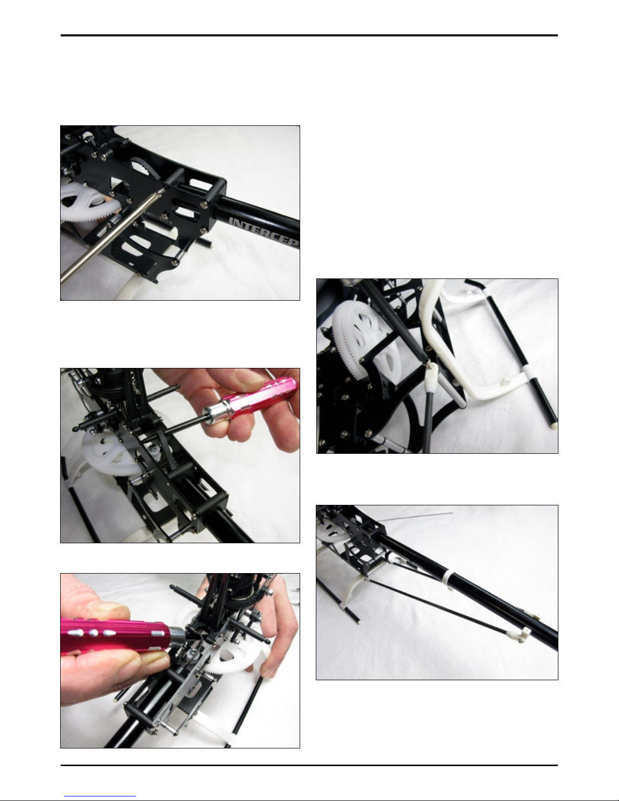
In order to easily place the belt over the
gear it is recommended that you unscrew
the bolt and screws on the boom holder. It
is then possible to push the boom further
into frame.
In order to align the belt correctly - using a
screwdriver rotate the belt 90° anti clock-
wise.
Then slip it over the gear.
Pull the boom back through and into place.
This should result in optimum belt tension.
To test the tension apply pressure onto one
side of the belt. It should not be so tight
as to not move and should not be so loose
as to touch itself. If adjustment is required
move the boom forward or back appropri-
ately. Tighten the boom holder screws once
the boom is correctly positioned.
Boom supports & taIl FIns
Insert rear aluminium rear spacer. Assemble
the boom supports and screw into place on
the spacer - on both sides. Use thread lock.
Screw the other end of the boom supports
into place on the horizontal tail n bracket.
Cut out horizontal n decal and stick to n.
Afx horizontal tail n to the bracket - use
a drop of thin CA to secure the ends of the
boom supports.
8
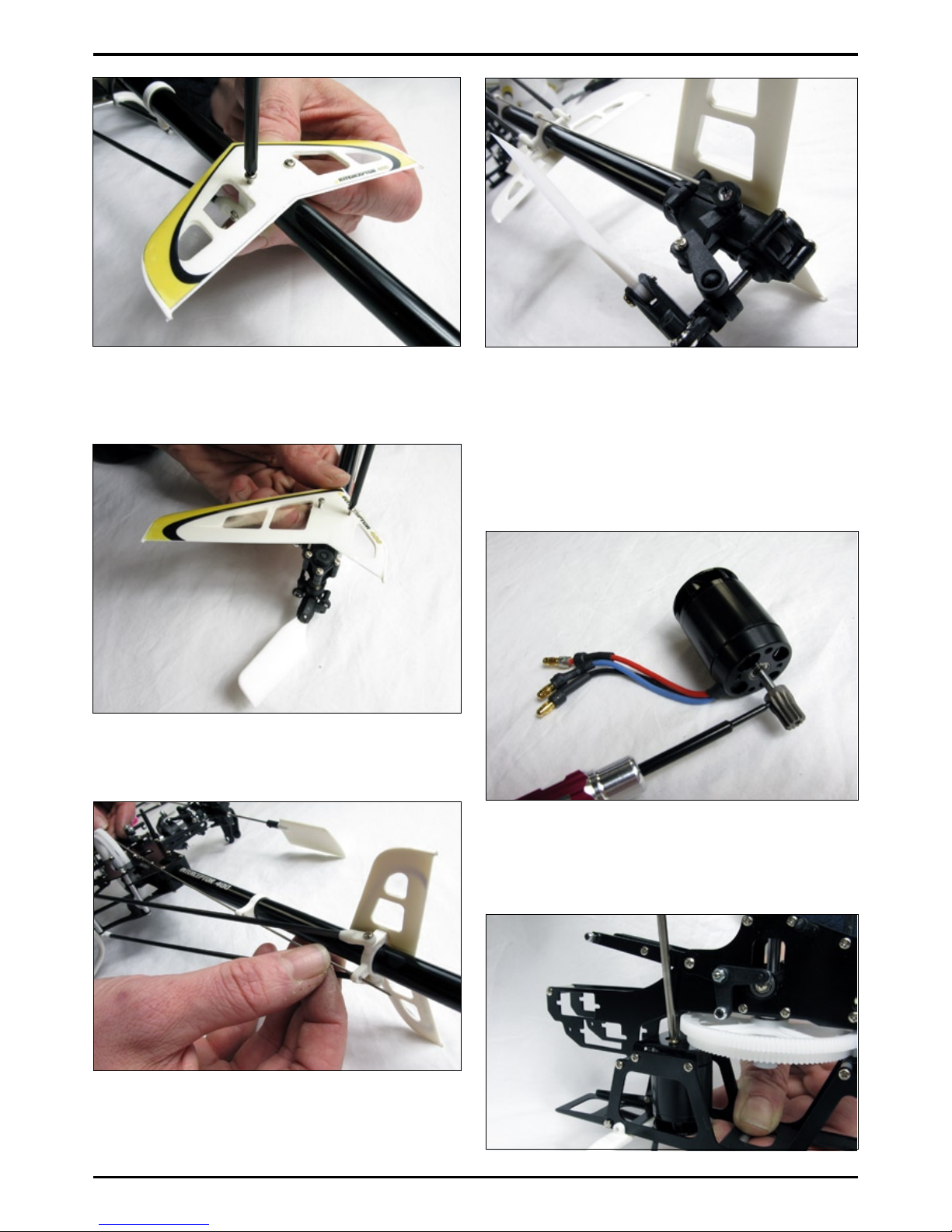
Cut out vertical tail n decal and stick
into place. Screw vertical tail n onto tail
mount.
Slide tail push rod through the holders on
the boom.
Screw on ball link and clip into place on tail.
InstallInG tHE motor
Attach a suitable pinion to motor shaft, use
a drop of thread lock on the grub screw.
Screw the motor into place on the helicop-
ters frame - use a drop of thread lock on the
mounting screws.
One mounting hole is elongated so as to
allow adjustment. The mesh of the gears
should crimp but not tear a piece of paper
when the gears are turned.
9

InstallInG Gyro, Esc and rX
We recommend installing your gyro and re-
ceiver inside the frame to ensure adequate
protection. Make sure they are easily ac-
cessible for adjustment and conguration.
Once your receiver is securely placed you
can route your wires carefully across the
frame of the INTERCEPTOR 400 ensur-
ing that they clear of all moving parts and
secured rmly with cable ties. The placing
and wiring is dependent on the components
you choose to use on your helicopter.
The ESC can be placed on the bottom or
side of the frame. Whichever is accessible
and within reach of the battery bay. Do not
cable tie into place - use adhesive foam.
InstallInG sErVos
Screw servos into place - don’t attach the
servo arms. Install the aileron servo rst.
Next install the pitch servo using the plastic
servo nuts to secure it into place. Bent nose
pliers can be useful at this point.
Install the elevator servo next.
The tail servo can be tricky so we recom-
mend placing the plastic servo nut onto the
servo prior to mounting as it can make it a
little easier.
10
Autres manuels pour Interceptor 400
1
Table des matières
Autres manuels helivol Jouet


