Heatrae Sadia HI-MAX STORE Manuel utilisateur

703034483_issue_02
HI-MAX STORE
Installation, operation and maintenance manual


page 1
Contents
1. Introduction
1.1 General
1.2 Symbols used
1.3 Abbreviations
1.4 Liabilities
2. Safety
2.1 General safety warnings
2.2 Recommendations
2.3 Specific safety instructions
3. Technical specifications
3.1 Product features
3.2 Dimensions and weight
3.3 Dimensions and features
3.4 Hydraulic diagrams
3.5 Hydraulic diagrams legend
3.6 Wiring Diagram
4. Before Installation
4.1 Installation regulations
4.2 Installation requirements
4.3 Transport and storage
4.4 Standard delivery
4.5 Positioning and access
4.6 Installation guidelines
5. Installation
5.1 HIU installation.
5.2 Cylinder and frame installation
5.3 Cylinder and HIU installation
5.4 Modesty panel installation
5.5 Modesty panel fitting instructions
6. Components
6.1 District control valve
6.2 Safety valve
6.3 Strainer
6.4 Plate heat exchanger
7. Commissioning
7.1 Commissioning district heating system
7.2 Filling the system
7.3 Product installation & service documentation.
8. Service
8.1 General
8.2 Fault finding
9. Spare parts
9.1 Spare parts - HI-MAX STORE

9.2 Spare parts - HI-MAX STORE HIU
10. Warranty
10.1 Warranty
page 2
1. Introduction
1.1 General
The following instructions are offered as a guide to the user and installer.
The installation must be carried out by a competent plumbing and electrical installer in
accordance with Building Regulations, The Building Standards (Scotland) Regulations 1990,
The Building Regulations (Northern Ireland), UK Water Regulations and IEE Electrical
Regulations.
The heating and hot water to your home are provided by the HI-MAX STORE HIU and
unvented cylinder.
Heat is supplied to the HI-MAX STORE HIU from the central boiler(s) installed elsewhere
in the building. The central boiler will provide heat to your HIU for your central heating and
domestic hot water.
The unit works in conjunction with an indirect domestic hot water cylinder to provide heating
and hot water to your taps. As such you must read these instructions in conjunction with
those for the cylinder.
The cylinder frame arrangement permits the cylinder to sit above a washing machine. The
HI-MAX STORE HIU is wall mounted and can be supplied with a first fix rail for ease of
installation.
The unit is supplied complete with all the necessary safety and control devices needed to
allow connection to the community heating system and the apartment's central heating and
hot water systems.
This appliance complies with the requirements of the CE marking directive.
The following instructions are offered as a guide to installation which must be carried out
by a competent plumbing and electrical installer in accordance with Building, Electrical and
Water Regulations.
1.2 Symbols used
In these instructions various risk levels are employed to draw the user's attention to particular
information. In doing so we wish to safeguard the user, avoid hazards and guarantee the
correct operation of the appliance.
DANGER
Risk of a dangerous situation causing serious physical injury.
WARNING
Risk of dangerous situation causing slight physical injury.
CAUTION
Risk of material
damage.
1.3 Abbreviations

#DHW - Domestic Hot Water
#T&P - Temperature & Pressure relief valve
#PRV - Pressure Reducing Valve
#Prv - Pressure relief valve
#Stv - Safety Tempering Valve
#HIU - Heat Interface Unit
#PICV - Pressure Independent Control Valve
1.4 Liabilities
Manufacturers liability
Our products are manufactured in compliance with the requirements of the various applicable
European Directives. This appliance complies with the requirements of the CE marking
directive and is Kiwa approved to show compliance with Building Regulations (part G,
section G3). In the interest of UK customers we are continuously endeavouring to make
improvements in product quality. All the specifications stated in this document are therefore
subject to change without notice.
Our liability as the manufacturer may not be invoked in the following cases:
#Failure to abide by the instructions on using the appliance.
#Faulty or insufficient maintenance of the appliance.
#Failure to abide by the instructions on installing the appliance.
Installer's liability
The installer is responsible for the installation and the commissioning of the appliance. The
installer must respect the following instructions:
#Read and follow the instructions given in the manuals provided with the appliance.
#Carry out installation in compliance with the prevailing legislation and standards.
#Perform the initial start up and carry out any checks necessary.
#Complete the commissioning checklist.
#Explain the installation to the user.
#If maintenance is necessary, warn the user of the obligation to check the appliance
and maintain it in good working order.
#It is the installers responsibility to ensure that all joints made in the factory are sound
after installation.
#Leave all the instruction manuals with the user.
Users liability
To guarantee optimum operation of the appliance, the user must respect the following
instructions:
#Read and follow the instructions given in the manuals provided with the appliance.
#Call on qualified professionals to carry out installation and initial start up.
#Ask the installer to explain the installation.
#Have the required checks and services carried out annually.
#Keep the instruction manuals in good condition and close to the appliance.
page 3
2. Safety
2.1 General safety warnings
DANGER
This unit becomes pressurised when in operation.


The combination of pressurisation and hot water could lead to serious physical injury if the safety
instructions in this manual are not adhered to.
The unit is also designed to work at district heating hydraulic pressures up to 16 bar g and
temperatures up to 90°C, which, if exposed to could lead to serious physical injury.
WARNING
#Only competent persons having received adequate training are permitted to work on the
appliance and the installation.
#Do not tamper with any of the safety valves or controls supplied with the cylinder.
#Before any work, switch off the electrical mains supply to the appliance and the water
mains.
#Do not switch on if there is a possibility that the water in the cylinder is frozen.
WARNING
#Do not adjust the safety tempering valve (Stv). This is factory set to prevent excessive hot
water temperatures reaching the taps in the event of a system failure.
The purpose of this valve should not be confused with that of a point of use mixing valve
which is fitted near to the tap to prevent scalding.
#Do not tamper with any of the safety valves fitted to the system. If a fault is suspected
contact a competent installer.
2.2 Recommendations
WARNING
When handling the unit, take appropriate precautions for the weight of the unit. Weights can be
found in section 3 page 7.
CAUTION
Annual maintenance is recommended by a competent
person.
The HWA Charter Statement requires that all members adhere to the following:
#To supply fit for purpose products clearly and honestly described.
#To supply products that meet, or exceed appropriate standards and building and water
regulations.
#To provide pre and post sales technical support.
#To provide clear and concise warranty details to customers.
page 4
2.3 Specific safety instructions
WARNING
#Under no circumstances should the factory fitted safety valves (Stv and Prv) be removed
by anyone other than a competent person.
The unit must not be run if either of these safety valves have been removed. Doing so will
invalidate any guarantee or claim.
#No control or safety valves should be tampered with or used for any other purpose.
#The Prv discharge pipe should not be blocked or used for any other purpose.
#Where a tundish is fitted, this should not be located adjacent to any electrical components.

CAUTION
Do not operate immersion heaters until the cylinder has been filled with water.
WARNING
#If water discharges from the temperature/ pressure relief valve on the cylinder, shut down
the boiler/immersion heaters.
Do not turn off any water supply.
Contact a competent installer for unvented water heaters to check the system.
#Do not tamper with any of the safety valves fitted to the system. If a fault is suspected
contact a competent installer.
#DO NOT bypass the thermal cut-out(s) in any circumstances.
WARNING
#The heat meter can be installed within the space provided inside the HI-MAX STORE
HIU.
Although most heat meters are now battery powered some are still provided with a mains
power supply.
In these instances it is important that the installer clearly indicates that there are two
power supplies to the HIU.
This appliance can be used by children aged from 8 years and above and
persons with reduced physical sensory or mental capabilities or lack of experience and
knowledge if they have been given supervision or instruction concerning use of the
appliance in a safe way and understand the hazards involved. Children shall not play
with the appliance.
Cleaning and user maintenance shall not be made by children without supervision.
Children must be supervised to ensure they do not play with the appliance.
#Water may drip from the discharge pipe of the pressure-relief device and this
pipe must be left open to the atmosphere.
#The pressure-relief device is to be operated regularly to remove lime deposits
and to verify that it is not blocked
#How hot water can be drained. (See Systemfit manual for more details)
#The type of characteristics of the pressure-relief device and how to connect it.
(See Systemfit manual for more details)
#A discharge pipe connected to the pressure-relief device is to be installed in a
continuously downward direction and in frost free environment.
Details on how to set the temperature controls for both immersion heaters and boiler
controls can be found in the Systemfit manual supplied.
page 5
3. Technical Specification
3.1 Product features

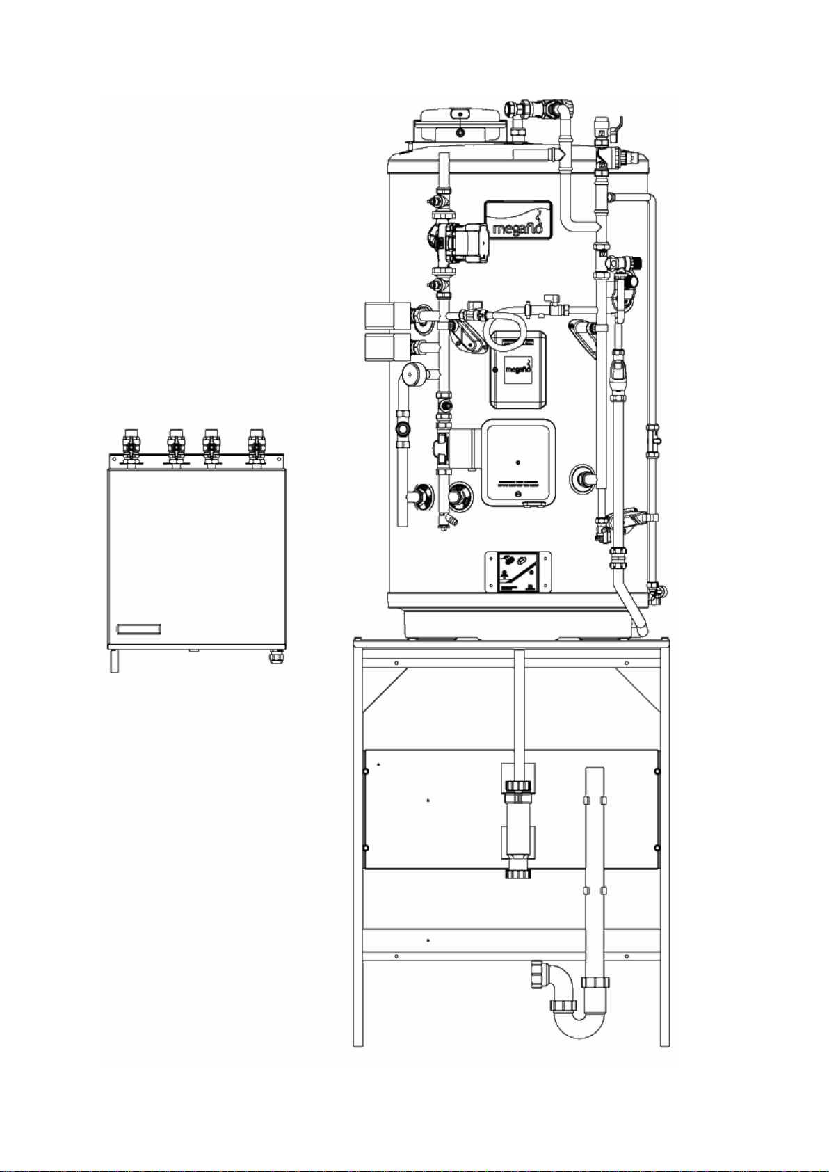
Fig 1. Product Features and Components for the HI-MAX STORE HIU
page 6
1. First fix rail bracket
2. 4 No. Fixing holes for first fix rail (Ø 7mm)
3. HIU mounting studs (M6) x 2. Supplied with HIU
4. 15mm central heating system safety valve 3 bar g

5. 230V on/off thermo actuator
6. DN 15 Frese Optima Compact pressure independent balancing and control valve
7. Brazed stainless steel plate heat exchanger
8. Test point to measure the pressure drop across the district control valve
9. Plate heat exchanger support bracket
10. Wall mounting bottom fixing holes Ø7mm (2 No.)
11. Test point to measure the pressure drop across the district control valve
12. Volume flow meter (for heat meter) spool piece 3/4" bsp x 110mm centres EN1434
13. 3/4"#bsp male Y strainer
14. Position of 1/4"# bsp heat meter flow sensor pocket (supplied by heat meter company)
15. Earth stud (M4)
16. Community (district) heating return - 3/4"# bsp male
17. Community (district) heating flow - 3/4" #bsp male
18. HWS primary return connection - 3/4" #bsp male
19. HWS primary flow connection - 3/4"# bsp male
20. Safety valve discharge pipe Ø15 mm
21. M12 cable gland (2 No.)
22. Actuator Cable Connector block
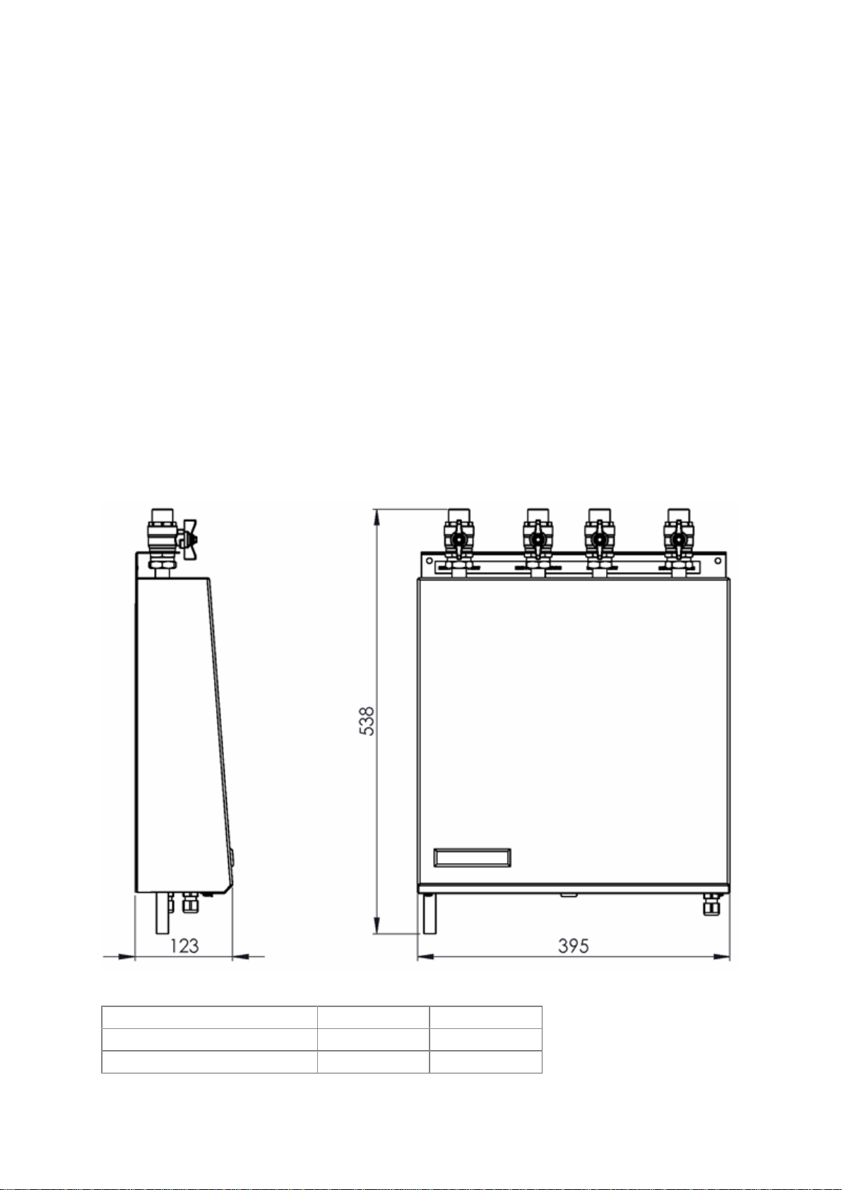
3.2 Dimensions and Weight
Fig 2. HI-MAX STORE HEAT INTERFACE UNIT
Unit Dry Weight (kg) Wet Weight (kg)
HI-MAX STORE 1st fix rail 1.6 1.6
HI-MAX STORE WITH CASINGS 11.2 13.0

Note: All dimensions are for reference only.
page 7
3.3 Dimensions and features - HI-MAX STORE
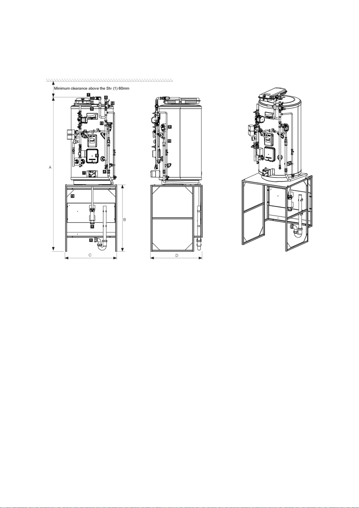
Fig 3. HI-MAX STORE Two heating zone model detailed
Cylinder size** 125i 145i 170i 210i 250i 300i
Dimension (mm)
A 2096 2217 2379 1584* 1855* xxxx
B 900 900 900 - - -
C 700 700 700 630 xxxx xxxx
D 700 700 700 700 xxxx xxxx
*Floor standing cylinder height (no frame).
Available depth for washing machine frame 580mm.
1. Domestic hot water flow 22mm
2. Cold feed connection (¼ turn isolation valve) 22mm
3. Balanced cold feed 22mm
4. Cylinder drain cock
5. Hepvo dry trap 32mm
6. Washing machine waste pipe 40mm
7. Immersion heater run back timer
8. Main 3kW immersion heater and thermostat enclosure IPX4
9. Temperature and pressure relief valve 10bar / 90-95°C
10. Tundish 15mm x 22mm
11. Combined expansion relief valve / check valve 8bar
12. Pressure reducing valve 3bar
Table des matières