3
Duct Furnace Ratings
A Rating Plate is attached to the front shroud of the duct furnace to identify the model and serial number of this
product. This plate must be left attached when the furnace is installed in the product for identification purposes. The
Rating Plate contains information including gas type, maximum and minimum input rating for this furnace assembly
and application, manifold pressure to provide rated Btuh input, maximum and minimum inlet supply gas pressure,
maximum and minimum airflow requirements, output capacity and electrical ratings for this specific module.
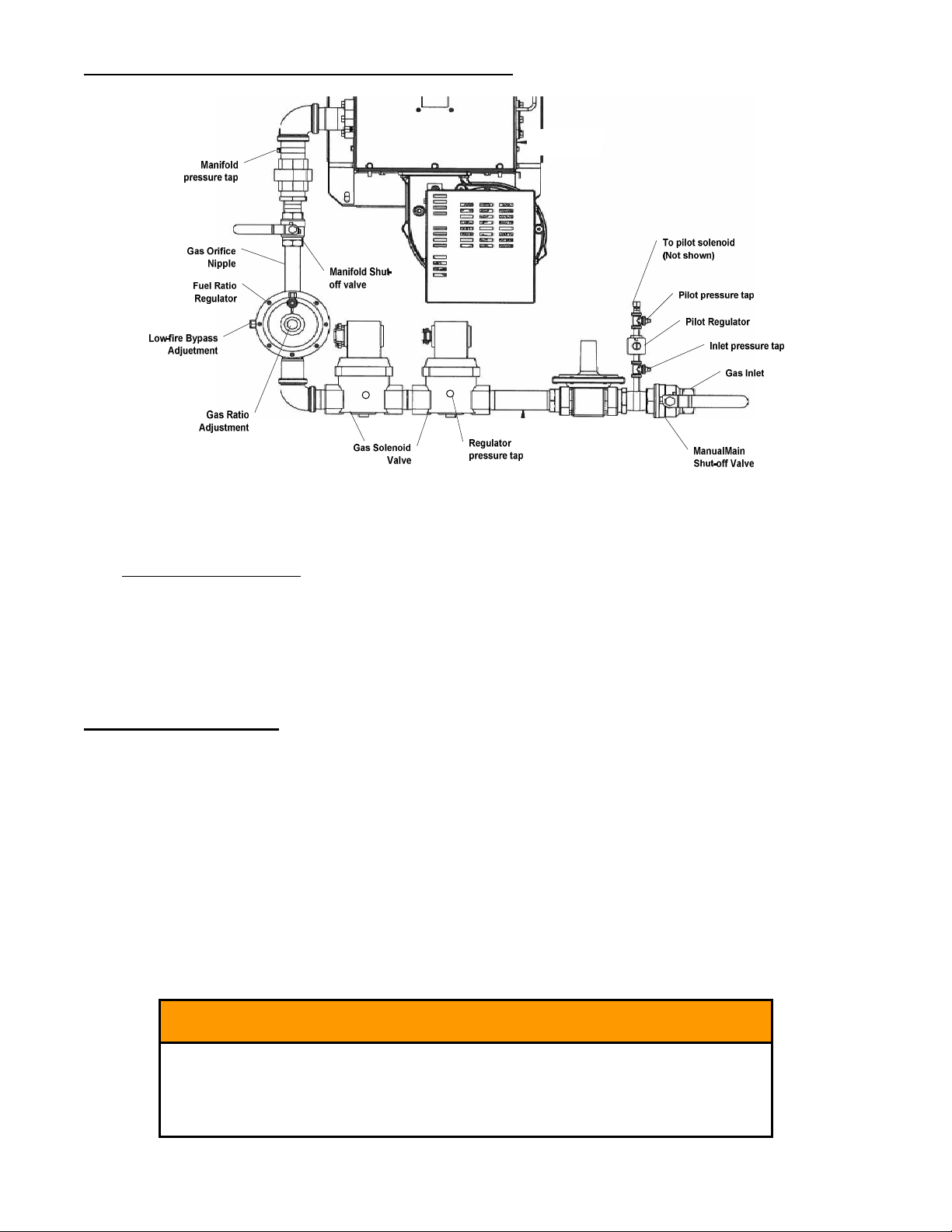
A Nameplate / Rating Plate is also attached to the power burner housing by the burner manufacturer, indicating the
input range, gas manifold pressure and electrical ratings for the power burner. The power burners used in these duct
furnaces typically have a wide range of input settings allowing a specific burner model to be used on more than one
size duct furnace. The burner has been orificed to provide the maximum input for this duct furnace at the manifold
pressure marked on the Furnace Rating Plate attached to the front shroud. Never adjust burner for inputs
exceeding the marked furnace maximum input.
Conditions of Application
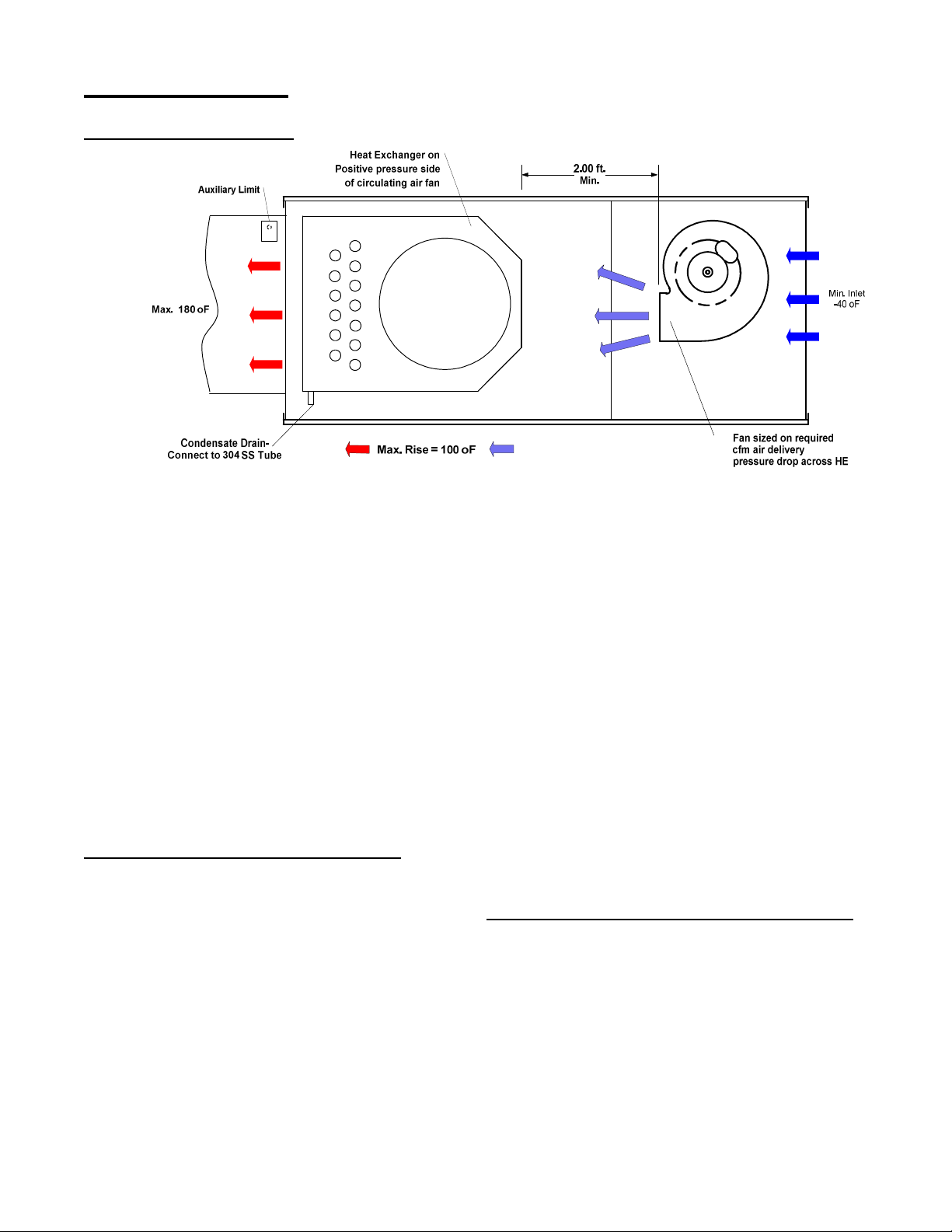
This duct furnace must be applied in accordance with the requirements of its listing as follows:
Maximum input ratings, duct and cabinet clearances to heat transfer surfaces, maximum and minimum
temperature rise and maximum and minimum airflow.
Installed on the positive side of the circulating air blower only.
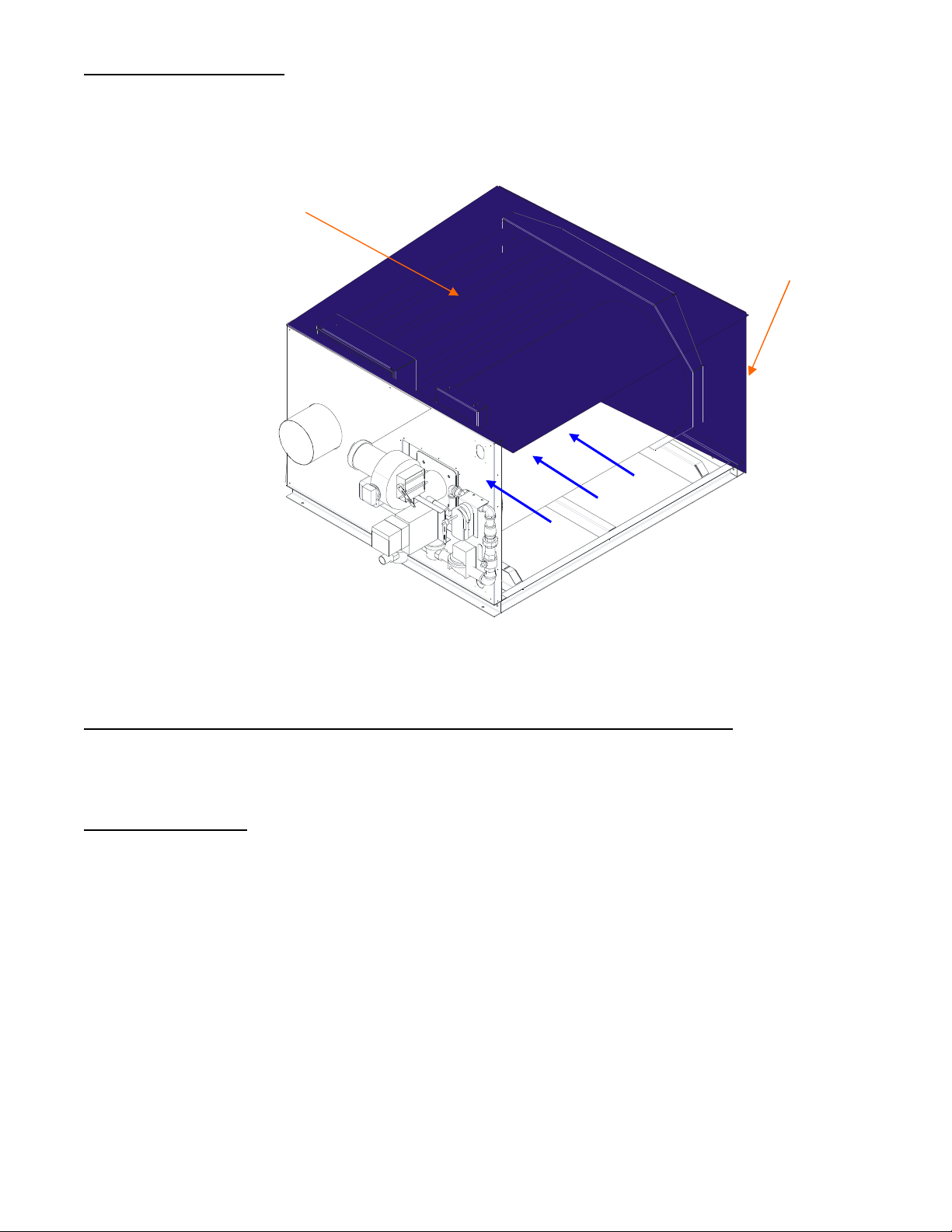
Installed in a Non-Combustible Duct or Cabinet and is not designed to have any portion of the heat
exchanger exposed outside the duct or cabinet in which it is housed. The furnace heat exchanger should be
sheathed to direct airflow over the heat exchanger surfaces (See Pg.4)
Have adequate airflow within the duct or cabinet, sufficiently well distributed to limit the maximum
temperature above inlet air temperature on heat exchanger surfaces as follows:
o409 Stainless Steel 1080 oF 304 Stainless Steel 1380 oF
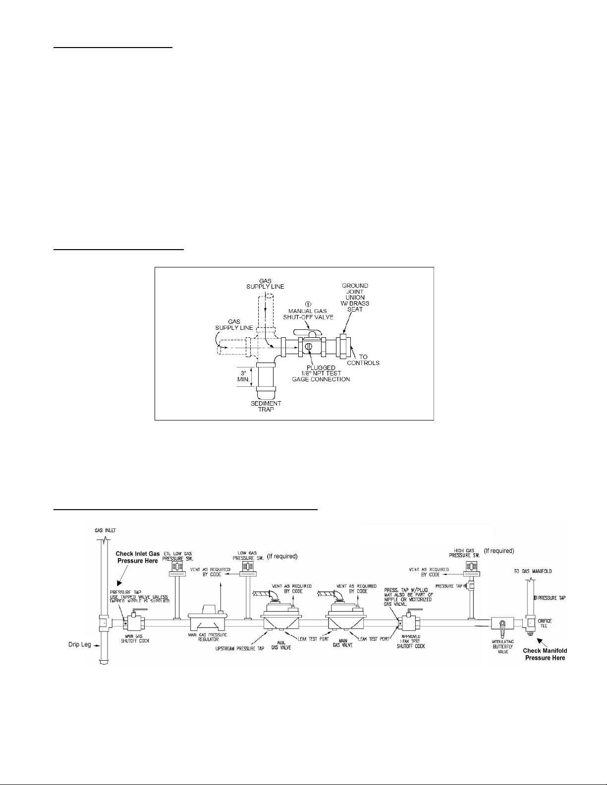
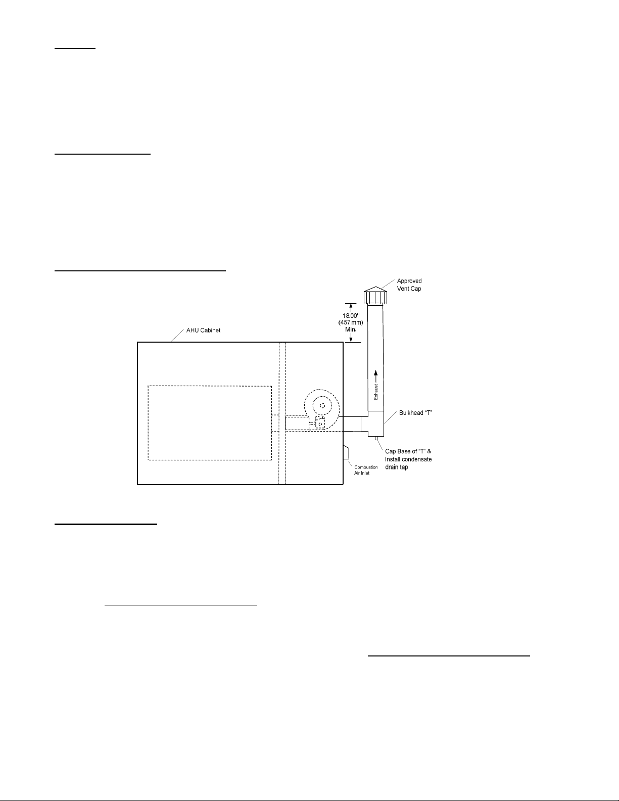
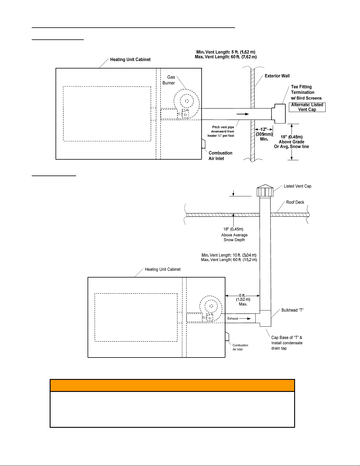
Specify Vent pipe the same diameter or cross-sectional area equal to flue collar or integral vent connector.
In constant volume airflow or modulating applications, burner turndown is limited to maintain the required
minimum 20 oF rise across the heat exchanger. For applications using 50% or more outside air, other
restrictions may apply. Refer to section “Airflow Consideration and Burner Turndown.
May be installed in series, provided the discharge air temperature does not exceed an average of 160 oF
above Room Temperature.
Clearances to combustibles as appropriate for the design, but in no case less than the following unless
determined by test as part of the manufacturer’s listing:
6 in. – Sides and back 2 in. – Bottom 36 in. – Top 24 in. – Front 2 in.- Vent
The equipment manufacturer shall provide adequate Installation and Operating Instructions for the completed air
handling unit to which the duct furnace is applied. The Installer/User Instructions, Gas Burner Instructions and Flame
Safeguard Instructions as well as wiring and piping diagrams provided in the information package shipped with this
duct furnace must be included with the finished product at the time of shipment. In addition, see labelling
requirements on Page 14.
Never adjust burner for an input rate exceeding the maximum input marked on the DUCT FURNACE
rating plate located on front shroud. Damage to the furnace and hazardous operation can result.