8
The constraints of the application will, to a
large extent, determine whether it is
preferable to use a single pipe gravity feed
system, or whether the two pipe pumped
system is more appropriate.
Where more than one appliance is to share
a common supply it will be necessary to use
a pressurised ring main system.
All pipe work must be constructed and
installed so that it does not permit the ingress
of air.
The construction, size, and position of the oil
storage tank must take account of the current
regulations, as well as suiting the
requirements of the installation.
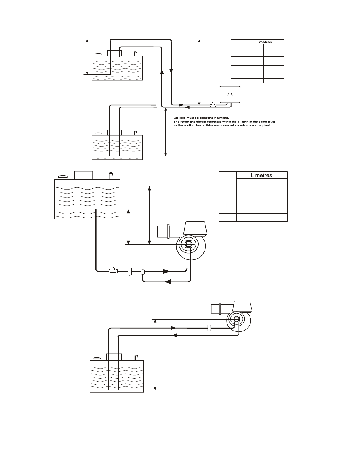
Please refer to figures 2 - 8 for additional
information.
Caution
On pumped systems always check that the
pump is correctly set up prior to running, and
always ensure that valves are open allowing
a free flow of oil through the system.
2.2 Fuel
In order to promote trouble free operating it is
necessary that the oil within the storage tank
and oil line does not fall below the cold filter
plugging point (cfpp), In the UK for class D
fuel (also referred to as gas oil),the critical
temperature is -4oC for summer grade.
The cfpp critical temperature for the winter
grade is -12oC. If summer grade fuel is
stored for winter use in areas prone to
severe frosts and low temperatures it will be
necessary to insulate or even heat the
supply tank and pipe work.
Note
The fuel supplier should be contacted prior to
installation so that any requirements
concerning delivery, transport, storage and
use can be addressed before work
commences.
Warning
The inlet pump pressure must not exceed a
maximum of 0.4 bar, this is because beyond
this point gas is liberated from the oil.
2.3 Storage tank
An externally painted steel storage tank to
BS 799 part 5 1987 or a medium density
polyethylene oil tank OFTEC certified to OFS
T-100 may be used. Local, national,
European and fire regulations must also be
complied with.
They must include the following.
A fuel level gauge (not made from glass) a
vent pipe with a diameter greater than that of
the filler and featuring a weatherproof
termination. A sludge valve.
An outlet valve situated at the opposite end
of the tank to the sludge valve.
A filler pipe connection situated at the
opposite end to the outlet valve.
The size of the storage tank must take
account of the estimated consumption and
any quantity price breaks offered by the oil
supplier.
It is preferable to install the tank outside,
however, if this is not practicable and the
tank has to be installed indoors advice must
be sought about its siting, especially so far
as fire regulations are concerned.
If a separate fire resistant chamber cannot
be provided for indoor installations, a
catchment pit with a capacity ten percent
greater than that of the storage tank must be
provided
Storage tanks can if necessary be sited on a
roof, but this is subject to special regulations
as well as local authority approval and
compliance with fire regulations, reference to
BS 5410 part 2 1978 & part 1 1997 is
strongly suggested.
It is advisable to leave the tank unpainted on
the inside, but to paint the outside with a
proprietary grade of anti-corrosive paint.
A galvanised or open topped tank is strictly
not allowed.
All oil storage tanks require a bund
The Control of Pollution Regulation ( Oil
Storage ) 2001 should be consulted prior to
installation
2.4 Single pipe system (gravity feed)
For installations where the oil tank is 200mm
or more above the level of the fuel pump the
principle of gravity feed may be used.
The draw off point for the supply to the
burner must not be positioned any lower than
100mm above the bottom of the tank.
Where a return valve is fitted this must be
tamper proof to prevent inadvertent
operation.