Harbor Freight Tools Haulmaster Instructions de montage

!"#"$%&'(%)*+#"$*%,$-%.$$/-00)))1.,(+&(2(*"3.$14&5
65,"7%&'(%$*4.8"4,7%#'//&($%,$-%/(&9'4$#'//&($:.,(+&(2(*"3.$14&5
Owner’s Manual & Safety Instructions
Save This Manual Keep this manual for the safety warnings and precautions, assembly,
operating, inspection, maintenance and cleaning procedures. Write the product’s serial number in the
back of the manual near the assembly diagram (or month and year of purchase if product has no number).
Keep this manual and the receipt in a safe and dry place for future reference. 21b
When unpacking, make sure that the product is intact
and undamaged. If any parts are missing or broken,
please call 1-888-866-5797 as soon as possible.
Copyright© 2021 by Harbor Freight Tools®. All rights reserved.
No portion of this manual or any artwork contained herein may be reproduced in
any shape or form without the express written consent of Harbor Freight Tools.
Diagrams within this manual may not be drawn proportionally. Due to continuing
improvements, actual product may differ slightly from the product described herein.
Tools required for assembly an d se rv ic e may n ot b e in cl uded.
Read this material before using this product.
Failure to do so can result in serious injury.
SAVE THIS MANUAL.

Page 2 ;&(%$*4.8"4,7%<'*#$"&8#=%/7*,#*%4,77%>?@@@?@AA?BCDC1 Item 58703
EF;6GH IJ6KFGLIM NFLMG6MFMO6FEE6NPQH
G,+7*%&2%O&8$*8$#
Safety ......................................................... 3
Assembly .................................................... 6
Operating Instructions ............................... 16
Operation ................................................... 16
Maintenance .............................................. 24
Parts List and Diagram .............................. 26
Reporting Safety Defects........................... 28
Warranty .................................................... 28
RFKMLMS%EHNPIQE%FMT%T6;LMLGLIME
This is the safety alert symbol. It is used to alert you to potential
personal injury hazards. Obey all safety messages that
follow this symbol to avoid possible injury or death.
Indicates a hazardous situation which, if not avoided,
will result in death or serious injury.
Indicates a hazardous situation which, if not avoided,
could result in death or serious injury.
Indicates a hazardous situation which, if not avoided,
could result in minor or moderate injury.
Addresses practices not related to personal injury.
!TO Volts Direct Current
FAmperes
WARNING marking concerning Risk
of Eye Injury. Wear ANSI-approved
safety goggles with side shields.
Read the manual before
set-up and/or use.
WARNING marking
concerning Risk of Fire.
Connect trailer wiring to
properly fused circuit only.

Page 3;&(%$*4.8"4,7%<'*#$"&8#=%/7*,#*%4,77%>?@@@?@AA?BCDC1Item 58703
EF;6GHIJ6KFGLIMNFLMG6MFMO6 FEE6NPQH
LNJIKGFMG%EF;6GH%LM;IKNFGLIM
K*,9%,77%#,2*$U%),(8"83#%,89%"8#$('4$"&8#1%%
Failure to follow the warnings and instructions may result in serious injury.
E,V*%,77%),(8"83#%,89%"8#$('4$"&8#%2&(%2'$'(*%(*2*(*84*1
The warnings, precautions, and instructions discussed in this instruction manual cannot cover all possible
conditions and situations that may occur. It must be understood by the operator that common sense and
caution are factors which cannot be built into this product, but must be supplied by the operator.
F##*5+7U%E,2*$U
1. Keep work area clean and dry.
Cluttered, damp, or wet work areas invite injuries.
2. Keep children away from work area.
3. Use eye protection. Wear ANSI-approved safety
impact eye goggles when assembling this Trailer.
4. Do not modify this Trailer, and do not use this
Trailer for a purpose for which it was not intended.
O&88*4$"&8%E,2*$U
1. Dress safely while connecting/disconnecting.
Do not wear loose clothing or jewelry, as they
can become caught in moving parts. Wear a
protective hair covering to prevent long hair from
becoming caught in moving parts. If wearing a
long-sleeve shirt, roll sleeves up above elbows.
Wearing safety work shoes is recommended.
2. Do not setup or use this Trailer if under the influence
of alcohol or drugs. Read warning labels on
prescriptions to determine if your judgement or
reflexes are impaired while taking drugs. If there
is any doubt, do not attempt to use this Trailer.
3. Stay alert. Watch what you are doing at
all times. Use common sense. Do not
setup or use this Trailer when you are tired
or distracted from the job at hand.
4. The tail light bulbs supplied with this Trailer are for a
12 volt DC (negative ground) electrical system only.
Do not attempt to power the Light Bulbs with
any other type or voltage electrical current.
5. Make sure the Hitch Coupler (2) and the
vehicle’s ball hitch (not included) are of equal
mating size (2") and are rated equal to or greater
than the weight of the Trailer and its payload.
6. Before each use, attach the Trailer’s Safety
Chain (1) to the towing vehicle. Attach the Safety
Chain to the towing vehicle’s rear bumper or
frame with equal length on each side and chains
crossed under the trailer tongue. Allow just enough
chain length for unrestricted turning. Do not
allow the Safety Chain to drag on the ground.
Q&,9"83%E,2*$U
1. Do not exceed the Trailer’s maximum
payload capacity of 1,720 lb.
2. Properly and safely secure the payload in the Trailer.
Load the Trailer evenly from side to side
with 60% of the load forward of the Axle.
3. Make sure the towing vehicle and its hitch are both
rated to safely tow the Trailer and its payload.
The towing capacity of the hitch is typically
stamped on the hitch drawbar.

Page 4 ;&(%$*4.8"4,7%<'*#$"&8#=%/7*,#*%4,77%>?@@@?@AA?BCDC1 Item 58703
EF;6GH IJ6KFGLIM NFLMG6MFMO6FEE6NPQH
I/*(,$"&8%E,2*$U
M&$*- Selected recommendations in this section are adapted from TOWING A TRAILER -
Being Equipped for Safety, published by NHTSA. For full details, see that document.
1. This Trailer is not a toy.
Do not allow children to play on or near this item.
2. Take time to practice before driving on main roads.
3. Never allow anyone to ride in or on the trailer.
4. Do not transport animals in this trailer.
P*2&(*%6,4.%W#*
1. Check Tire condition and air pressure.
2. Make sure wheel lug nuts/bolts
are properly tightened.
3. Make sure hitch, coupler, draw bar, and other
equipment that connect the trailer and the tow
vehicle are properly secured and adjusted.
4. Make sure wiring is properly connected — not
touching the road, but loose enough to make turns
without disconnecting or damaging the wires.
5. Make sure all running lights, brake lights,
turn signals, and hazard lights are working.
6. Check that all items are securely
fastened on and in the trailer.
7. Be sure the trailer jack, tongue support, and any
attached stabilizers are raised and locked in place.
8. Check load distribution to make sure
the tow vehicle and trailer are properly
balanced front to back and side to side.
9. Check side- and rear-view mirrors to
make sure you have good visibility.
10. Check routes and restrictions
on bridges and tunnels.
11. Make sure you have wheel chocks and jack stands.
12. Check trailer for loose bolts and nuts,
structural cracks and bends, and any
other condition that may affect its
safe operation. Do not use the Trailer
even if minor damage appears.
S*8*(,7%X,897"83
1. Use the driving gear that the towing vehicle
manufacturer recommends for towing.
2. Drive at moderate speeds. This will place
less strain on your tow vehicle and trailer.
Trailer instability (sway) is more likely to
occur as speed increases. T&%8&$%*Y4**9%
ZB%5"7*#%/*(%.&'(%).*8%$&)"83%$.*%G(,"7*(1
3. Avoid sudden stops and starts that can
cause skidding, sliding, or jackknifing.
4. Avoid sudden steering maneuvers that might
create sway or undue side force on the trailer.
5. Slow down when traveling over bumpy roads,
railroad crossings, and ditches.
6. Make wider turns at curves and corners.
Because your trailer’s wheels are closer to the
inside of a turn than the wheels of your tow vehicle,
they are more likely to hit or ride up over curbs.
7. To control swaying caused by air pressure changes
and wind buffeting when larger vehicles pass from
either direction, release the accelerator pedal to slow
down and keep a firm grip on the steering wheel.
P(,["83
1. Allow considerably more distance for stopping.
2. If you have an electric trailer brake controller and
excessive sway occurs, activate the trailer brake
controller by hand. Do not attempt to control
trailer sway by applying the tow vehicle brakes;
this will generally make the sway worse.
3. Always anticipate the need to slow down.
To reduce speed, shift to a lower gear
and press the brakes lightly.
F44*7*(,$"&8%,89%J,##"83
1. When passing a slower vehicle or changing lanes,
signal well in advance and make sure you
allow extra distance to clear the vehicle
before you pull back into the lane.
2. Pass on level terrain with plenty of clearance.
Avoid passing on steep upgrades or downgrades.
3. If necessary, downshift for improved
acceleration or speed maintenance.
4. When passing on narrow roads, be careful not
to go onto a soft shoulder. This could cause
your trailer to jackknife or go out of control.

Page 5;&(%$*4.8"4,7%<'*#$"&8#=%/7*,#*%4,77%>?@@@?@AA?BCDC1Item 58703
EF;6GHIJ6KFGLIMNFLMG6MFMO6 FEE6NPQH
T&)83(,9*#%,89%W/3(,9*#
1. Downshift to assist with braking on downgrades
and to add power for climbing hills.
2. On long downgrades, apply brakes at intervals to
keep speed in check. Never leave brakes on for
extended periods of time or they may overheat.
3. Some tow vehicles have specifically calibrated
transmission tow-modes. Be sure to use the
tow-mode recommended by the manufacturer.
P,4["83%W/
1. Put your hand at the bottom of the steering wheel.
To turn left, move your hand left.
To turn right, move your hand right.
2. Back up slowly.
3. Because mirrors cannot provide all of the
visibility you may need when backing up,
have someone outside at the rear of the
trailer to guide you whenever possible.
4. Use slight movements of the steering wheel
to adjust direction. Exaggerated movements
will cause greater movement of the trailer.
5. If you have difficulty, pull forward and realign
the tow vehicle and trailer and start again.
J,(["83
1. Try to avoid parking on grades.
2. If possible, have someone outside
to guide you as you park.
3. I84*%#$&//*9=%+'$%+*2&(*%#."2$"83%"8$&%J,([-
a. Have someone place blocks on the
downhill side of the trailer wheels.
b. Apply the parking brake.
c. Shift into Park.
(first or reverse gear for manual transmissions)
d. Then remove your foot from the brake pedal.
Following this parking sequence is important to
make sure your vehicle does not become locked in
Park because of extra load on the transmission.
4. P*2&(*%'84&'/7"83%,%$(,"7*(-
a. Place blocks at the front and rear of the
trailer tires to ensure that the trailer does not
roll away when the coupling is released.
b. An unbalanced load may cause the
tongue to suddenly rotate upward;
therefore, before uncoupling, place jack stands
under the rear of the trailer to prevent injury.
GKFLQ6K%QLO6MELMS%MIGLO6
Some states may consider this Trailer a vehicle requiring registration, licensing, and titling.
Check with your State DMV for information and guidance on registering, licensing, and titling the Trailer.
N,"8$*8,84*%E,2*$U
1. Maintain labels and nameplates on the trailer.
These carry important information. If
unreadable or missing, contact Harbor
Freight Tools for a replacement.
2. Replacement parts and accessories: when
servicing, use only identical replacement parts.
Only use accessories intended for use
with this Trailer. Approved accessories are
available from Harbor Freight Tools.
3. Maintain this Trailer with care. Keep this Trailer
clean and dry for better and safer performance.
4. For your safety, service and maintenance should
be performed regularly by a qualified technician.
5. When not in use, store Trailer in a
dry location to inhibit rust. Lock up Trailer,
and keep out of reach of children.
6. Position Trailer on flat, level, hard surface and
chock both Tires before folding/unfolding.
7. Do not fold up the trailer without assistance.
8. Before standing up the trailer, properly secure the
rear and front section together. See page 25.
%EF!6%GX6E6%LMEGKWOGLIME1
Page 6 ;&(%$*4.8"4,7%<'*#$"&8#=%/7*,#*%4,77%>?@@@?@AA?BCDC1 Item 58703
EF;6GH IJ6KFGLIM NFLMG6MFMO6FEE6NPQH
E/*4"2"4,$"&8#
Maximum Capacity Payload 1,720 lb.
Bed Dimensions 4 ft. x 8 ft.
Hitch 2" Ball Size, Class II
Lug Nuts Torque to 85 - 90 ft-lb
Axle U-Bolt Nuts Torque to 15 ft-lb
Tires
F##*5+7U%L8#$('4$"&8#
%K*,9%$.*%6MGLK6%LNJIKGFMG%EF;6GH%LM;IKNFGLIM%#*4$"&8%,$%$.*%+*3"88"83%&2%$."#%5,8',7%
"847'9"83%,77%$*Y$%'89*(%#'+.*,9"83#%$.*(*"8%+*2&(*%#*$%'/%&(%'#*%&2%$."#%G(,"7*(1
M&$*- For additional information regarding the parts listed in the
following pages, refer to Parts List and Diagram on page 26.
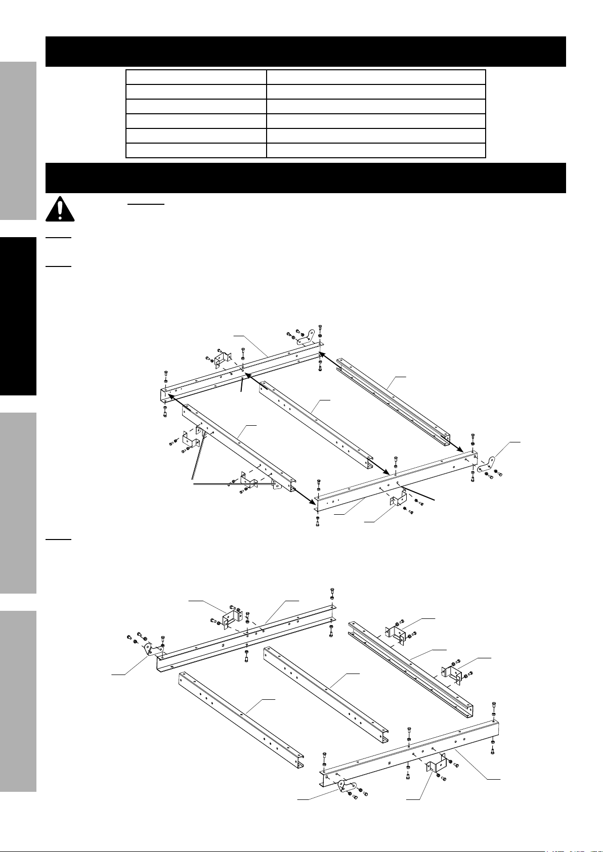
M&$*- ;"83*(%$"3.$*8%.,(9),(*%2"(#$1%%F2$*(%,##*5+7U=%#<',(*%,89%$"3.$*8%.,(9),(*1
1. On a flat, level surface, lay out Front Right Side Rail (37), Front Left Side Rail (26), Front Cross Member (39),
and 2 Cross Members (32).
Lay out 2 Front Hinge Plates (flat) (27) and 4 Stake Brackets (40). Assemble
F##*5+7*%#&%$.,$%
$.*#*%+(,4[*$#%,(*%
,837*9%"8),(91
;KIMG%I;%GKFLQ6K
O6MG6K%I;%GKFLQ6K
\D
\C
\]
\]
;7,$%
X"83*%
]C
]A Z^
M&%+&7$%_ZZ`
&8%+&$$&5
M&%+&7$%_ZZ`
&8%+&$$&5
M&$*- ;"83*(%$"3.$*8%.,(9),(*%2"(#$1%%F2$*(%,##*5+7U=%#<',(*%,89%$"3.$*8%.,(9),(*1
2. Lay out Rear Right Side Rail (34), Rear Left Side Rail (31), and 3 Cross Members (32).
Lay out 2 Rear Hinge Plates (bent) (28) and 4 Stake Brackets (40). Assemble
K6FK%I;%GKFLQ6K
O6MG6K%I;%GKFLQ6K
\>
]@
Z^
Z^
Z^
Z^
\]
\]
\]
\Z
P*8$%
X"83*%
]@

Page 7;&(%$*4.8"4,7%<'*#$"&8#=%/7*,#*%4,77%>?@@@?@AA?BCDC1Item 58703
EF;6GHIJ6KFGLIMNFLMG6MFMO6 FEE6NPQH
3. Connect front and rear sections together
by attaching Cross Members using 2 sets
4. Connect Hinge Plates together using 2 sets
ZZ
ZZ
ZZ ZZ
;KIMG%E6OGLIM
K6FK%E6OGLIM
5. R"$.%,##"#$,84*=%$'(8%$.*%,##*5+7U%&V*(1
6. Attach Tow Bar Brackets (45) to Front Left
and Right Side Rails using 4 sets of Hex
Bolts M10 x 30 and Nuts M10 (36).
M&$*- ;"83*(%$"3.$*8%.,(9),(*%2"(#$1%%F2$*(%,##*5+7U=%#<',(*%,89%$"3.$*8%.,(9),(*1
7. Place Tow Bars (5) into brackets on Front Cross Member and Side Rails.
8.
9. Attach Tow Bar T-Plate (3) and Coupler Base (4) to the ends Tow Bars,
ZZ
B
\
Z
Z\
Z\
B
ZZ
ZZ
Z]
Z]
\A
ZB

Page 8 ;&(%$*4.8"4,7%<'*#$"&8#=%/7*,#*%4,77%>?@@@?@AA?BCDC1 Item 58703
EF;6GH IJ6KFGLIM NFLMG6MFMO6FEE6NPQH
10. Place Right Spring Hanger (41) and Left Spring
Hanger (19) over Right and Left Side Rails.
11. Secure using:
12. Attach Right Caster Bracket (23) and Left
Caster Bracket (22) to Spring Hangers, using
13. Attach 4 Casters (21) to Caster Brackets.
\B
\B
\A
Z>
ZZ
ZZ
ZZ
]>
]>
]\
14. Attach Fender Brackets (24) to left and
right Fenders (25) using four sets of
15. Attach Fender assemblies to left and
right Spring Hangers using four sets of
ZZ
ZZ
]B
]Z
16. Attach Springs (8) to left and right Spring
Hangers with spring eyes facing forward,
M12 (20).
Q*,V*%$.*#*%P&7$#%7&&#*%
$*5/&(,("7U%$&%,77&)%/(&/*(%
,##*5+7U%"8%$.*%8*Y$%#$*/#1
17. Place Axle (7) on top of Springs.
Align depressions on Axle with
protrusions on Springs.
18. Remove nuts from Axle U-Bolts (9).
On both ends of the Axle, place
Spring Plates (6) under Springs and
insert Axle U-Bolts (9) down over
Axle and through mounting holes in
Spring Plates. Adjust Spring Plates
slightly to allow holes to line up.
19. Secure Axle U-Bolt with nuts, then tighten
in step 16 to secure Spring assemblies.
G&(<'*%FY7*%W?P&7$%8'$#%$&%>B%2$1?7+1
]^
]^
C
@
A
D

Page 9;&(%$*4.8"4,7%<'*#$"&8#=%/7*,#*%4,77%>?@@@?@AA?BCDC1Item 58703
EF;6GHIJ6KFGLIMNFLMG6MFMO6 FEE6NPQH
20. Remove Dust Caps (18). Place a
wood dowel into back of hub assembly,
then tap dowel to push Dust Cap
off, being careful not to remove
bearing. Repeat for other Tire.
>@
21. Remove Castle Nuts (15) and
Washers (14) from each end of Axle.
22. Place Tire and Washer on Axle.
23. Thread Castle Nut onto Axle until tire starts spinning
with slight resistance, then back off slightly and
line up gaps in Castle Nut with holes in Axle.
24. Insert Cotter Pin (16) through Castle Nut and Axle.
Bend pins in opposite directions to secure tire.
25. Repeat on other side.
26. Replace Dust Caps, tapping with
rubber mallet to seat them.
27. Lubricate zerk fittings on back of Hub Assemblies
with a heavy weight bearing grease.
28. O.*4[%$&(<'*%&8%Q'3%M'$#1%%G.*U%
5'#$%+*%$&(<'*9%$&%@B%?%D^%2$?7+1%%
>@
>B
>A
>\
>Z

Page 10 ;&(%$*4.8"4,7%<'*#$"&8#=%/7*,#*%4,77%>?@@@?@AA?BCDC1 Item 58703
EF;6GH IJ6KFGLIM NFLMG6MFMO6FEE6NPQH
29. R"$.%,##"#$,84*=%$'(8%$.*%,##*5+7U%("3.$%#"9*%'/1
30. Attach Coupler (2) to Coupler Base, using 2 sets of
Bolts M12 x 75 and Nuts M12 (20).
R.*8%"8#$,77"83%$.*%2(&8$%P&7$=%$.(*,9%"$%
$.(&'3.%$.*%4*8$*(%7"8[%&2%$.*%E,2*$U%O.,"8%_>`%
$&%#*4'(*%O.,"8%$&%"8#"9*%&2%O&'/7*(1%
31. Lock the Coupler Trigger, using its
Locking Pin and R-Clip.
32. Attach Light Brackets (33) to Rear Side Rails using
four sets of Bolts M10 x 20 and Nuts M10 (44).
33. Remove nuts from back of Right Tail Light (30R).
Attach Right Tail Light to Right Light Bracket, secure
with nuts.
34. Remove nuts from back of Left Tail Light (30L).
Attach License Plate Bracket (29), along with
Left Tail Light, to Left Light Bracket, secure with
nuts.
35. Run wires on back of Side Running Lights (38)
through center holes at the front ends of
Side Rails. Attach Side Running Lights
using Screws and Nuts (46).
\\
\^K
\^Q
]D
\\
\@
ZA
\@
]
>
]^
ZZ
ZZ
ZA
Autres manuels pour Haulmaster
1
Table des matières
Autres manuels Harbor Freight Tools Véhicule utilitaire


