2
Table of Contents
1 Page 3
2 Page 3
3 Page 4
Page 4
Page 5
Page 5
Page 6
4 Page 6
Page 7
Page 7
Page 9
Page 8
5 Page 9
Page 10
6 Page 10
Page 11
Page 11
Page 12
Page 12
Page 13
7 Page 13
Page 13
Page 13
Page 14
Page 14
8 Page 15
Page 15
Page 15
Page 15
Page 16
9 Page 16
10 Page 17
11 Page 18
Page 18
Page 19
Page 20
Page 20
Page 21
Page 23
12 Page 23
Page 23
Page 24
Page 24
13 Page 25
Page 26
14 Page 27
15 Page 27
16 Page 28
17
Warnings
General Information
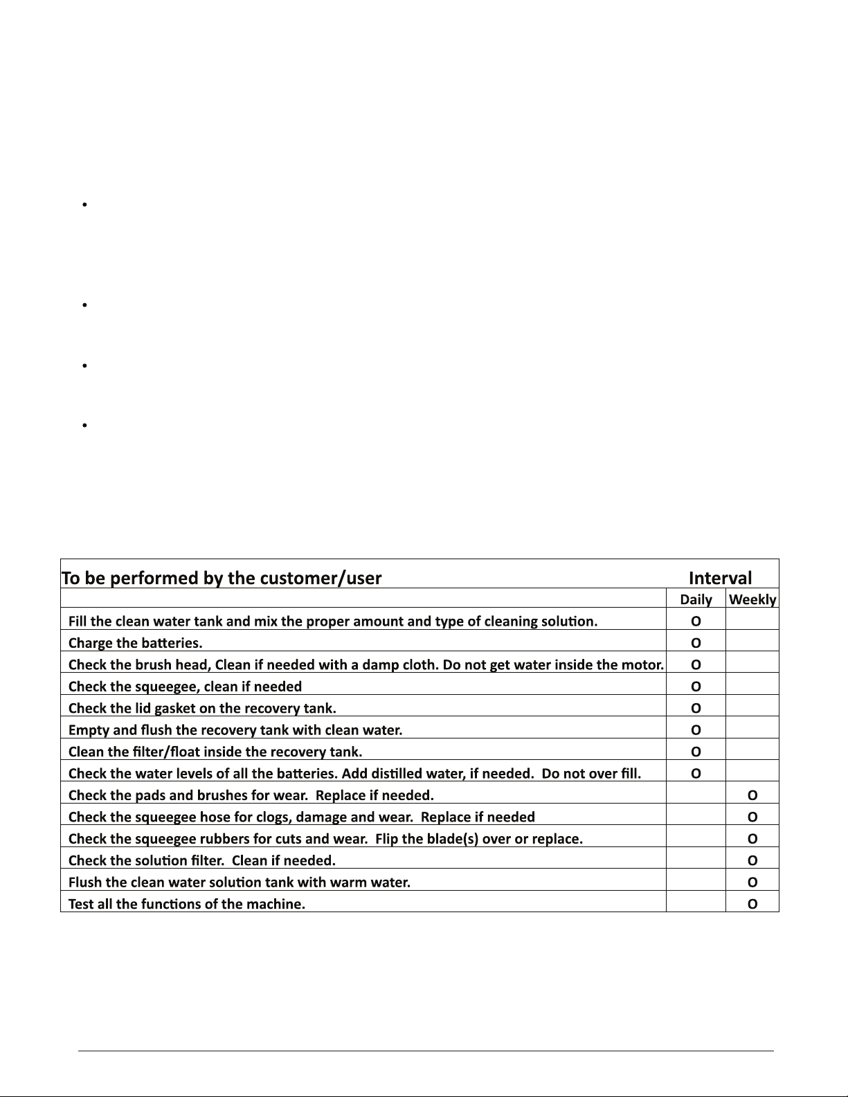
Maintenance Intervals
3.1 System Maintenance K (Customer)
3.2 System Maintenance I (125 hours of operation) 3.3
System Maintenance II (250 hours of operation) 3.4
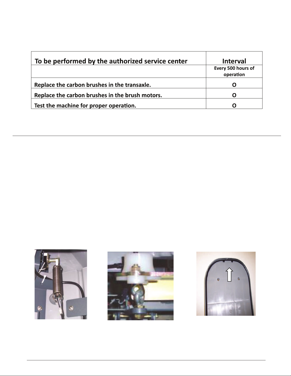
Hammerhead System Maintenance S
(500 hrs of operation, at least yearly)
Squeegee Cable and Recovery Tank Gasket
4.1 Squeegee Adjustment (First Version)
4.2 Squeegee Adjustment (new Style)
4.3 Squeegee Lift Cable, Micro Switch, Vacuum Motor
4.4 Squeegee Wheel Adjustment
Brush Head (Disk Brushes) Connections
5.1 Brush Motor Information
Brush Head Transport Position
6.1 Brush Switch
6.2 Brush Pressure Adjustment on the Disk Models
6.3 Brush Pressure (Disk Decks)
6.4 Cylindrical Brush Head Electrical Connections
6.5 Cylindrical Brush Head Adjustment
Drive and Wheels - General Data
7.1 Electric Brake
7.2 Transaxle Motor
7.3 Carbon Brushes
7.4 Drive Potentiometer
Water Supply
8.1 Solenoid
8.2 Solution Filter
8.4 Solution Flow Rates
8.5 Water Pump
The Last Error
Table of Error Codes and Information
Battery Charger
11.1 Operating Instructions
11.2 Charger Error Codes
11.3 Charger Trouble Shooting
11.4 Charger Maintenance Points
11.5 Programming The Charger
11.6 Replacing The Charger Harness
Batteries
12.1 Maintaining Wet Lead Acid Batteries
12.2 Load Testing Batteries
12.3 Hydrometer Testing
Fuse Locations Version 2
13.1 Controller Version 3
Controller Connections
Trouble Shooting Controller
Contactor Harness
Contactor Wiring Page 29
Page 6
HAMMERHEAD