Haag-Streit BX 900 Manuel utilisateur

1
DEUTSCHENGLISH FRANÇAIS ITALIANO ESPAÑOL NEDERLANDS
PORTUGUÊS SVENSKA
DEUTSCHENGLISHFRANÇAISITALIANOESPAÑOLNEDERLANDS PORTUGUÊS
SVENSKA
© HAAG‑STREIT AG, 3098 Koeniz, Switzerland ‑ HS‑Doc. no. 1500.7220449‑04090 – 2021 – 08
INSTRUCTIONS FOR USE
Photo slit lamp
BX 900®
9. Edition / 2021 – 08

2
DEUTSCHENGLISH FRANÇAIS ITALIANO ESPAÑOL NEDERLANDS
PORTUGUÊS SVENSKA
© HAAG‑STREIT AG, 3098 Koeniz, Switzerland ‑ HS‑Doc. no. 1500.7220449‑04090 – 2021 – 08
INSTRUCTIONS FOR USE
Photo slit lamp
BX 900®
9. Edition / 2021 – 08
Preface
Thank you for choosing a Haag-Streit device. Provided you comply carefully with the
regulations in these instructions for use, we can guarantee reliable and trouble-free
use of our product.
WARNING!
Read the instruction manual carefully before commissioning this product.
It contains important information regarding the safety of the user and
patient.
NOTE!
For USA only: Federal law restricts this device to sale by or on the order
of a physician or licensed practitioner.
WARNING!
This device is equipped with high intensity light emitting diodes.
Excessive exposure of patients in treatment with certain medication may
lead to phototoxic adverse reactions, due to higher photosensitivity.

3
DEUTSCHENGLISH FRANÇAIS ITALIANO ESPAÑOL NEDERLANDS
PORTUGUÊS SVENSKA
DEUTSCHENGLISHFRANÇAISITALIANOESPAÑOLNEDERLANDS PORTUGUÊS
SVENSKA
© HAAG‑STREIT AG, 3098 Koeniz, Switzerland ‑ HS‑Doc. no. 1500.7220449‑04090 – 2021 – 08
Contents
• 1 Safety...................................................................................................................................................4
◦ 1.1 Comments on these instructions for use........................................................................................4
◦ 1.2 Ambient conditions.........................................................................................................................4
◦ 1.3 Shipment and unpacking ...............................................................................................................4
◦ 1.4 Installation warnings ......................................................................................................................5
◦ 1.5 Operation, environment .................................................................................................................5
◦ 1.6 Light toxicity ...................................................................................................................................5
◦ 1.7 Disinfection ....................................................................................................................................6
◦ 1.8 Warranty and product liability ........................................................................................................6
◦ 1.9 Reporting obligation.......................................................................................................................6
◦ 1.10 Description of symbols.................................................................................................................7
• 2 Intended purpose / intended use .......................................................................................7
◦ 2.1 Device description..........................................................................................................................7
◦ 2.2 Medical purpose.............................................................................................................................7
◦ 2.3 Principles of operation ...................................................................................................................8
◦ 2.4 Clinical benefit................................................................................................................................8
• 3 Introduction .....................................................................................................................................9
◦ 3.1 Overview........................................................................................................................................9
◦ 3.2 Photo components.......................................................................................................................10
◦ 3.3 Lens barrel...................................................................................................................................11
◦ 3.4 Camera housing...........................................................................................................................11
◦ 3.5 Flash unit FU 01...........................................................................................................................11
◦ 3.6 LED illumination...........................................................................................................................11
◦ 3.7 Overview of the LED illumination unit upper part.........................................................................11
◦ 3.8 Blue filter......................................................................................................................................11
◦ 3.9 Shutter .........................................................................................................................................11
◦ 3.10 Background illumination.............................................................................................................12
◦ 3.11 Power supply .............................................................................................................................12
• 4 Device assembly / installation ...........................................................................................12
◦ 4.1 Instrument base with weight compensation facility......................................................................12
◦ 4.2 Setting the weight compensation facility......................................................................................13
◦ 4.3 Switching on the compensation facility ........................................................................................13
◦ 4.4 Switching off the compensation facility ........................................................................................13
◦ 4.5 Regulating the clearance of the slit width controls.......................................................................13
◦ 4.6 Attaching/removing a camera ......................................................................................................13
• 5 Commissioning ...........................................................................................................................13
◦ 5.1 Switching on the device ...............................................................................................................13
• 6 Operation.........................................................................................................................................14
◦ 6.1 Setting the eyepieces...................................................................................................................14
◦ 6.2 Preparing the patient....................................................................................................................14
◦ 6.3 Operating the device....................................................................................................................14
◦ 6.4 Background illumination (flash)....................................................................................................15
◦ 6.5 Photo diaphragm pre-selection.................................................................................................... 15
◦ 6.6 Setting the filters & diaphragms................................................................................................... 15
◦ 6.7 Fixation star................................................................................................................................. 16
◦ 6.8 Microscope and eyepiece............................................................................................................ 16
◦ 6.9 Operating the Flash unit FU 01 ...................................................................................................16
• 7 Decommissioning ..................................................................................................................... 17
• 8 Technical data ............................................................................................................................. 17
◦ 8.1 Slit illumination............................................................................................................................. 17
◦ 8.2 Stereo microscope....................................................................................................................... 18
◦ 8.3 Instrument base........................................................................................................................... 18
◦ 8.4 Dimensions.................................................................................................................................. 18
◦ 8.5 Flash illumination unit FU 01 .......................................................................................................18
◦ 8.6 Mirror and diaphragm component ...............................................................................................18
◦ 8.7 Lens barrel................................................................................................................................... 19
◦ 8.8 Camera........................................................................................................................................ 19
• 9 Maintenance.................................................................................................................................. 19
◦ 9.1 Device inspection ........................................................................................................................ 19
◦ 9.2 Changing the flash tube............................................................................................................... 20
◦ 9.3 Servicing...................................................................................................................................... 20
◦ 9.4 Replacing the fuses..................................................................................................................... 20
◦ 9.5 Cleaning and disinfection ............................................................................................................21
◦ 9.6 Replacing the illumination mirror .................................................................................................21
◦ 9.7 Dust cover ................................................................................................................................... 21
• 10 Appendix ...................................................................................................................................... 21
◦ 10.1 Accessories / functionals parts / detachable parts / consumables ............................................21
◦ 10.2 Legal regulations .......................................................................................................................22
◦ 10.3 Classification ............................................................................................................................. 22
◦ 10.4 Disposal..................................................................................................................................... 22
◦ 10.5 Observed standards ..................................................................................................................22
◦ 10.6 Information and manufacturer's declaration concerning electromagnetic compatibility (EMC) .23

4
DEUTSCHENGLISH FRANÇAIS ITALIANO ESPAÑOL NEDERLANDS
PORTUGUÊS SVENSKA
© HAAG‑STREIT AG, 3098 Koeniz, Switzerland ‑ HS‑Doc. no. 1500.7220449‑04090 – 2021 – 08
1Safety
DANGER!
Failure to comply with these instructions may result in material damage
or pose a danger to patients or users.
WARNING!
These warnings must absolutely be complied with to guarantee safe
operation of the product and to avoid any danger to users and to
patients.
NOTE!
Important information, please read carefully.
1.1 Comments on these instructions for use
NOTE!
In these instructions for use the point is used as decimal separator.
1.2 Ambient conditions
Temperature −40 °C ... +70 °C
Air pressure 500 hPa ... 1060 hPa
Transport
Relative humidity 10 % ... 95 %
Temperature −10 °C ... +55 °C
Air pressure 700 hPa ... 1060 hPa
Storage
Relative humidity 10 % ... 95 %
Temperature +10 °C ... +35 °C
Air pressure 800 hPa ... 1060 hPa
Use
Relative humidity 30 % ... 90 %
1.3 Shipment and unpacking
• Before unpacking the device, check whether the packaging shows traces of
improper handling or damage. If this is the case, notify the transport company
that delivered the goods to you.
• Unpack the device together with a representative of the transport company.
Make a report of any damaged parts. This report must be signed by you and by
the representative of the transport company.
• Leave the device in the packaging for a few hours before unpacking it
(condensation).
• Check the device for damage after it is unpacked.
• Return defective devices in the appropriate packaging.
• Store packaging material carefully so that it can be used for potential returns or
when moving.
• The slit lamp and headrest must be installed on an electrically insulated,
fireproof table top.
• The rail covers (a) prevent the slit lamp from tilting.
• Check that the connection parts of the accessories are in the correct position
(screw connections, quick-release fasteners).

5
DEUTSCHENGLISH FRANÇAIS ITALIANO ESPAÑOL NEDERLANDS
PORTUGUÊS SVENSKA
DEUTSCHENGLISHFRANÇAISITALIANOESPAÑOLNEDERLANDS PORTUGUÊS
SVENSKA
© HAAG‑STREIT AG, 3098 Koeniz, Switzerland ‑ HS‑Doc. no. 1500.7220449‑04090 – 2021 – 08
1.4 Installation warnings
WARNING!
•Do not modify this device without authorization of the manufacturer.
Installation and repairs may only be performed by trained
specialists.
• Any third-party device must be connected in compliance with the EN
60601-1 standard.
• Only original Haag-Streit spare parts may be used.
• Use of this device adjacent to or stacked with other equipment
should be avoided because it could result in improper operation. If
such use is necessary, this device and the other equipment should
be observed to verify that they are operating normally.
• Grounding reliability can only be achieved when unit is connected to
a hospital grade receptacle. (Not valid for EU countries).
• The device should be set up in such a way that the plug is always
easily accessible and the device can easily be disconnected from
the mains.
1.5 Operation, environment
DANGER!
Never use the device in potentially explosive environments where
volatile solvents (alcohol, petrol, etc.) and flammable anaesthetics are in
use.
WARNING!
• The device must be switched off after every use. Otherwise there is
a risk of overheating when a protective dust cover is used.
• This device must not be operated near of high frequency surgical
equipment and the radio frequency shielded room of a medical
electrical system for magnetic resonance imaging, where the
intensity of electromagnetic disturbances is high.
• Portable radio frequency communications equipment (including
peripherals such as antenna cables and external antennas) should
be used no closer than 30 cm (12 inches) to any part of the device,
including cables specified by Haag-Streit. Otherwise, degradation of
the performance of this device could result.
NOTE!
• This device must only be operated by qualified personnel. The
owner is responsible for their training.
• This device may only be used in accordance with the instructions in
the 'Intended purpose / intended use' chapter.
1.6 Light toxicity
WARNING!
• The light from this device may be dangerous. The risk of eye
damage increases with the radiation period and number of pulses.
Exposure at maximum output of longer than 70 seconds with the
LED illumination and 70 pulses with the flash source will exceed the
hazard guideline value.
•Using a 90 D lens reduces the exposure time to 9 seconds and the
number of pulses to 10.
NOTE!
• The radiation times and number of total pulses of all light sources
are cumulative.
• If the intensity of any of the light sources is reduced to 50% of the
maximum intensity, the illumination time or number of pulses to
reach the guideline value for radiation for the light source in question
is doubled. This linear relationship can be used to determine the
illumination time to reach the guideline value for radiation for the
combination of slight sources at various brightness settings.
• The guideline value for the evaluated irradiation of the retina is 10 J/
cm2.
• Nevertheless, we recommend keeping the intensity of the light
reaching the patient's retina to the minimum possible for the

6
DEUTSCHENGLISH FRANÇAIS ITALIANO ESPAÑOL NEDERLANDS
PORTUGUÊS SVENSKA
© HAAG‑STREIT AG, 3098 Koeniz, Switzerland ‑ HS‑Doc. no. 1500.7220449‑04090 – 2021 – 08
respective diagnosis. Children, aphakes and people suffering from
eye conditions are most at risk.
• An increased risk may also occur if the retina is exposed to the
same or a similar device with a visible light source within 24 hours.
This specially applies if the retina has been photographed with a
flashbulb in advance.
• When the flash illumination is used, the emission exceeds the Group
2 limit of parameter “weighted retinal visible and infrared thermal
radiance, LVIR-R“ as specified by EN ISO 15004-2: 2007 but does
not exceed the limit “retinal thermal” as specified by ICNIRP 2013.
Since this retinal exposure limit is not exceeded in case of normal
operation, the device can be regarded as safe for the patient’s eye
when operated within the limits specified by Haag-Streit.
1.7 Disinfection
NOTE!
The device can, but does not need to be disinfected. For more
information, please refer to the 'Maintenance' chapter.
1.8 Warranty and product liability
• Haag-Streit products must be used only for the purposes and in the manner
described in the documents distributed with the product.
• The product must be treated as described in the ‘Safety’ chapter. Improper
handling can damage the product. This would void all guarantee claims.
• Continued use of a product damaged by incorrect handling may lead to personal
injury. In such a case, the manufacturer will not accept any liability.
• Haag-Streit does not grant any warranties, either expressed or implied, including
implied warranties of merchantability or fitness for a particular use.
• Haag-Streit expressly disclaims liability for incidental or consequential damage
resulting from the use of the product.
• This product is covered by a limited warranty granted by your seller.
• For USA only: This product is covered by a limited warranty, which may be
reviewed at www.haag-streit-usa.com.
1.9 Reporting obligation
NOTE!
Any serious incident that has occurred in relation to the device must be
reported to Haag-Streit and the competent authority of the Member
State in your country.
7
DEUTSCHENGLISH FRANÇAIS ITALIANO ESPAÑOL NEDERLANDS
PORTUGUÊS SVENSKA
DEUTSCHENGLISHFRANÇAISITALIANOESPAÑOLNEDERLANDS PORTUGUÊS
SVENSKA
© HAAG‑STREIT AG, 3098 Koeniz, Switzerland ‑ HS‑Doc. no. 1500.7220449‑04090 – 2021 – 08
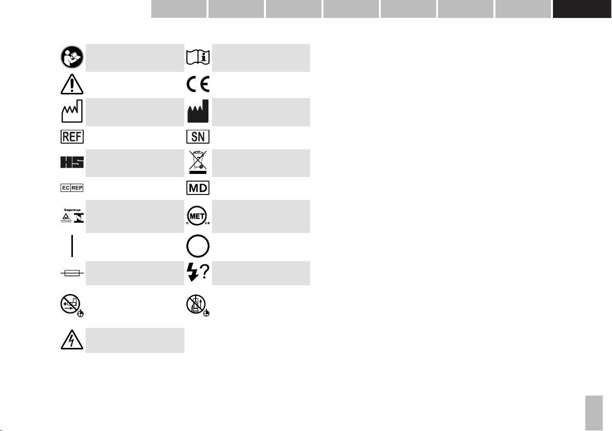
1.10 Description of symbols
Follow instruction for use Read the instructions for use
attentively
General warning, read the
accompanying documentation
European certificate of
conformity
Date of manufacture Manufacturer
Haag-Streit reference number Serial number
Trademark of the manufacturer
Haag-Streit AG
Notes on disposal, see the
'Disposal' chapter
Listed European Authorized
Representative Medical Device
Testsymbol of TÜV Rheinland
with approval for INMETRO
Brasil
MET Listed Mark with approval
for USA and Canada
On (Power) Off (Power)
Fuse Flash Test
After turning off the FU 01 flash
unit, wait at least 15 seconds
before the flash cable is
removed.
After turning off the FU 01 flash
unit, wait at least 15 seconds
before the slide is opened.
Warning: Dangerous voltage
2Intended purpose / intended use
A slit lamp biomicroscope is intended for use in eye examination. It is used to aid in
the diagnosis and documentation of diseases or trauma which affect the structural
properties of the eye.
2.1 Device description
The devices of the slit lamp are made up of:
• Stereo biomicroscope
• Slit illumination
• Instrument base
• Headrest and chin rest
The illumination system and a biomicroscope are mounted to an instrument base
operated by joystick. The single joystick allows horizontal and vertical displacement
of the slit lamp across the examination table. Both elements, the illumination system
and the biomicroscope, can be swiveled progressively across the pivot,
independently of one another.
A sturdy headrest is attached to the table. Both the table and the chin rest are
adjustable in height to provide a comfortable, yet sturdy examination position to the
patient, outside of the device's range of motion. As this device operates non-
invasively it only comes into contact with the patient at the chin rest and forehead
band.
2.1.1 Intended users
Users are qualified medical professionals such as ophthalmologists, optometrists,
opticians, nurses and researchers or other qualified specialists as permitted by local
legislation.
2.2 Medical purpose
This device has the following medical purpose:
•Diagnosis and monitoring of diseases of the anterior segment of the eye
•Diagnosis and monitoring of injuries of the anterior segment of the eye
• Investigation of the anatomy and physiological or pathological state of the
anterior segment of the eye

8
DEUTSCHENGLISH FRANÇAIS ITALIANO ESPAÑOL NEDERLANDS
PORTUGUÊS SVENSKA
© HAAG‑STREIT AG, 3098 Koeniz, Switzerland ‑ HS‑Doc. no. 1500.7220449‑04090 – 2021 – 08
2.2.1 Indications
The use of the slit lamp is indicated for the following medical conditions:
• Local and systemic diseases affecting the eye
• Lesions and defects of the anterior segment
• Acute infections and inflammations
• Presence of intraocular foreign bodies
• Other traumata of the eye
2.2.2 Part of the body
The slit lamp is intended for the examination of the human eye, specifically the
anterior segment of the eye (i.e., lids, lashes, conjunctiva, cornea, anterior chamber,
iris, and lens).
2.2.3 Patient population
This device is intended for use on human patients with the physical ability to sit in
front of a slit lamp with their head resting against the headrest in a steady position
and the mental ability to follow instructions.
2.2.4 Contraindications
There are no known contraindications.
2.3 Principles of operation
• The slit lamp implements the principle of focal illumination: The focal point of the
microscope and the illumination coincide.
• The microscope arm and the illumination arm are mounted on an instrument
base: Both can be swivelled independently around the same vertical axis.
• The instrument base can be moved in all three axes.
• When illuminating transparent media with a narrow, sharp slit, an 'optical
section' can be magnified and viewed through the microscope.
• The patient's head is fixed to a height-adjustable headrest holder so that the
examination can be carried out quickly and as comfortably as possible for both
doctor and patient.
2.3.1 Operating environment
The slit lamp is intended to be used in professional health care facilities such as
hospitals, physician's, optometrist's and optician's practices. For optimal use of the
slit lamp, the ambient lighting should be attenuated to improve image contrast. In
case of transillumination of the iris or for viewing details at great magnification at a
narrow slit, it may be necessary to completely darken the room.
2.4 Clinical benefit
The use of the slit lamp allows for the systematic examination of the eye under
magnification, thus permitting the diagnoses of pathologies that may have otherwise
remained unidentified and could have lead to blindness if left untreated.
The clinical benefits of the product outweigh the remaining residual risks to the
patient.

9
DEUTSCHENGLISH FRANÇAIS ITALIANO ESPAÑOL NEDERLANDS
PORTUGUÊS SVENSKA
DEUTSCHENGLISHFRANÇAISITALIANOESPAÑOLNEDERLANDS PORTUGUÊS
SVENSKA
© HAAG‑STREIT AG, 3098 Koeniz, Switzerland ‑ HS‑Doc. no. 1500.7220449‑04090 – 2021 – 08
3Introduction
The slit lamp consists of an illumination and a binocular microscope. The instrument
base can be used to move the entire device in front of the eyes. The illumination
offers a large number of setting options to make the practically invisible areas in the
eye visible. There is also a range of accessories available for the slit lamp to allow
special diagnosis possibilities in addition to the general examinations.
3.1 Overview
1. LED illumination unit upper part
2. Lever for grey filter and red
removal filter
3. Scale for angled position of the slit
image (5° increments)
4. Illumination mirror
5. Magnification changer
6. Mounting screw for the stereo
microscope
7. LED background illumination with
swivel bracket
8. Illumination unit / microscope
angle scale
9. Illumination arm locking screw
10. Microscope arm locking screw
11. Slit width controls
12. Weight compensation screws
13. Diffusor
14. Slit length / diaphragm scale
15. Slit length, slit rotation, blue filter
and fixation star control, knob for
rotating the slit
16. Cover screw for accessories pin
17. Bayonet connector for accessories
18. Stereo microscope with eyepieces
19. Breath shield
20. Fastening pin for breath shield
21. Thread for fixing the tonometer
22. Centring screw
23. Inclination angle latch 0°-20°
24. Joy stick base locking screw
25. Axle
26. Rail cover
27. Control lever
28. Slide plate

10
DEUTSCHENGLISH FRANÇAIS ITALIANO ESPAÑOL NEDERLANDS
PORTUGUÊS SVENSKA
© HAAG‑STREIT AG, 3098 Koeniz, Switzerland ‑ HS‑Doc. no. 1500.7220449‑04090 – 2021 – 08
3.2 Photo components
29. Flash cable (with tube and flash
tube connection)
30. Optical light guide for background
illumination
31. Pivoting mirror
32. Rotating knob for diaphragm pre-
selection
33. Rotating knob for diaphragm
preview actuation
34. Rotating knob for aperture preview
35. Flash unit FU 01
36. Flash tube housing
37. Flash tube
38. Lens barrel
39. Camera housing
40. Camera cable
41. Ocular with double cross hairs
42. Mirror and diaphragm component
43. Cable trigger key for mirror/
diaphragm component
44. Trigger key with cable
Autres manuels pour BX 900
2
Table des matières
Autres manuels Haag-Streit Équipement de diagnostic


