GSI Group 2000 Series Manuel utilisateur

1
Series 2000 Downwind Heater
Downwind Series 2000
Centrifugal Heater
Installation And
Operating Instructions
Owner's
Manual
PNEG-591
MODEL # CH__ - __ __ - __ __ - 2 __ (HIGH)
MODEL # CL__ - __ __ - __ __ - 2 __ (LOW)

2
Series 2000 Downwind Heater

3
Series 2000 Downwind Heater TABLE OF CONTENTS
Safety ..........................................................................................................................4
Series2000HeaterInstallation.........................................................................................6
High Temperature Heater Specifications................................................................6
Low Temperature Heater Specifications................................................................6
AirPressureSwitchandTemperatureSensorBox......................................................7
TransitionHi-Limit Installation................................................................................7
Bin Configuration/Operating Temperature Table...................................................8
Heater Unit Wiring..................................................................................................9
Secondary Heater Unit Wiring................................................................................9
Machine To Earth Ground.....................................................................................10
Proper Installation Of The Ground Rod.................................................................10
Previously Installed Units......................................................................................10
Fuel Connection For Liquid Propane Models.........................................................11
Fuel Connection For Propane Vapor Models........................................................11
Fuel Connection For Natural Gas Models............................................................11
Installing Optional Humidity Sensor....................................................................12
Series2000OperatingProcedure....................................................................................13
Power Up..............................................................................................................13
Normal Operating Displays With Heater Not Running..........................................14
Starting The Dryer.................................................................................................15
Setting Gas Pressure ............................................................................................15
BTU's Per Gauge Pressure (PSI) 10-15 hp Models (Approximate)......................17
BTU's Per Gauge Pressure (PSI) 20-40 hp Models (Approximate).....................18
BTU's Per Gauge Pressure (PSI) Lo-temp Models (Approximate).....................20
Adjusting the Air Pressure Switch.......................................................................21
Adjusting The Vaporizor........................................................................................22
Running The Dryer...............................................................................................22
Programming Set Points.......................................................................................23
Programming Hours To Shutdown.......................................................................24
Drying Grain In The Hours To Shutdown Mode...................................................24
Run Hours Display...............................................................................................24
Multiple Heater Notes............................................................................................24
Modulating Valve Operation.................................................................................25
Factory Configuration..................................................................................................26
ConfigurationDipSwitches(NormallyDone At GSI)............................................26
Error Conditions..........................................................................................................27
Limit Switches......................................................................................................27
MultipleHeater Error Conditions...........................................................................27
Misc Error Numbers..............................................................................................27
Series 2000 Heater Service..........................................................................................28
Series2000 Wiring Diagram.........................................................................................29
Series 2000 Heater Parts............................................................................................30
10-15hpDWHighTemp Heater...............................................................................30
10-15hpDWLowTemp Heater................................................................................31
20-30hpDWHighTempHeater................................................................................32
20-30hp DW Low Temp Heater...........................................................................33
40hp DW High Temp Heater...............................................................................34
40hp DW Low Temp Heater................................................................................35
DW Heater Control Box......................................................................................36
Air Switch Temperature Sensor Box.....................................................................37
DW Propane Vapor Pipetrain..............................................................................38
DW Natural Gas Pipetrain...................................................................................39
DW Propane Vapor Hi-Lo Pipetrain....................................................................40
DW Natural Gas Hi-Lo Pipetrain........................................................................41
DW LP Pipetrain.................................................................................................42
Warranty.......................................................................................................................44

4
Series 2000 Downwind Heater
SAFETY
SAFETY FIRST
General Safety Statements
The GSI Group Inc’s Principal concern is
yoursafetyandthesafety of others associated with
grain handling equipment. We want to keep you
as a customer. This manual is to help you under-
stand safe operating procedures and some prob-
lems which may be encountered by the operator
and other personnel.
Asownerand/oroperator, itisyourrespon-
sibility to know what requirements, hazards and
precautions exist and inform all personnel associ-
ated with, or in the area of the product. Safety
precautions may be required from the personnel.
This product is ideal for the conditioning of corn,
soy beans or other select grains. Avoid any alter-
ation to the equipment, such alterations may pro-
duce a very dangerous situation, where serious in-
jury or death may occur. If a decal is damaged or missing contact:
The GSI Group Inc.
1004 E. Illinois St.
Assumption, IL 62510
217-226-4421
A free replacement will be sent to you.
DANGER indicates an imminentlyhazardoussituation
which, if not avoided, will result in death or serious in-
jury
WARNING indicates a potentially hazardous situation
which , if not avoided, could result in death or serious
injury.
CAUTION indicates a potentially hazardous situation
which, if not avoided, may result in minor or moderate
injury.
CAUTION used without the safety alert symbol indi-
cates a potentially hazardous situation which, if not
avoided, may result in property damage.
BE ALERT!
Danger!
Personnel operating or
working around electrical
equipment should read this
manual. This manual must be delivered with
equipment to its owner. Failure to read this
manual and its safety instructions is a misuse
of the equipment.
CAUTION
CAUTION
WARNING
DANGER
This is the safety alert symbol.
It is used to alert you to poten-
tial personal injury hazards.
Obey all safety messages that
follow this symbol to avoid possible in-
jury or death.
The GSI Group Inc. recommends that you
contact your local power company and have a rep-
resentative review your installation so your wir-
ing will be compatible with their system and so
thatyouwillhaveadequatepowersuppliedtoyour
unit.

5
Series 2000 Downwind Heater SAFETY
Roof Damage Warning And Disclaimer
GSI DOES NOT WARRANT ANY ROOF DAMAGE
CAUSEDBYEXCESSIVEVACUUMORINTERNALPRES-
SURE FROM FANS OR OTHER AIR MOVING SYSTEMS.
ADEQUATE VENTILATION AND/OR "MAKEUP AIR" DE-
VICES SHOULD BE PROVIDED FOR ALL POWERED AIR
HANDLING SYSTEMS. GSI DOES NOT RECOMMEND
THE USE OF DOWNWARD FLOW SYSTEMS (SUCTION).
SEVERE ROOF DAMAGE CAN RESULT FROM ANY
BLOCKAGE OF AIR PASSAGES. RUNNING FANS DUR-
ING HIGH HUMIDITY/COLD WEATHER CONDITIONS
CAN CAUSE AIR EXHAUST OR INTAKE PORTS

6
Series 2000 Downwind Heater
SPECIFICATIONS
Heater Size
Inside Height
Inside Width
Inside length
10-15
30.1/4"
19.1/2"
24"
20-30
33.1/4"
21.3/4"
24"
40
33.1/4"
23.11/16"
24"
Heater Dimensional Specifications
Hi-Temp Hi-Temp Lo-Temp Model
10-15HP 20-40HP All units
All Models BTU Rating 2225000 4500000 500000
Weight 145 145 135
Liquid Models Maximum Fuel flow (GPH) 24 49 N/A
Orifice size 0.2188 0.3125 N/A
Mod Valve Bypass Orifice Blue Aluminum Yellow
Minimum operating pressure 1 1 N/A
Maximum operating pressure 15 15 N/A
Minimum line size 3/8" 3/8" N/A
Vapor Models Maximum Fuel flow(CFH) 931 1898 210
Orifice size 0.2188 0.3125 0.109
Mod Valve Bypass Orifice Blue Aluminum Yellow
Minimum operating pressure 1 1 1
Maximum operating pressure 15 15 15
Minimum line size 3/8" 3/8" 1/2"
Natural Gas Maximum Fuel flow(CFH) 2496 4643 500
Models Orifice size 0.3438 0.4688 0.156
Mod Valve Bypass Orifice Aluminum Aluminum Green
Minimum operating pressure 0.5 0.5 1
Maximum operating pressure 7 7 7
Minimum line size 1.1/4" 1.1/4" 1"
CentrifugalHeaterSpecifications

7
Series 2000 Downwind Heater HEATER INSTALLATION
Air Pressure Switch and
Temperature Sensor Box
Installation
1. Using air switch box as a
guide, mark 2 holes on ple-
num side wall appproximately
24" to right of transition cen-
tered up and down in plenum.
2. Drill air switch filter hole 5/8"
diameter for snug fit. Drill tem-
perature sensor hole 5/8" or
largerto accommodate mounting
nut.
3. Mount Box to Bin using (4)
self drilling screws
4. Caulk between housing and side-
wall to seal.
Air Switch Box Assembly
1. Mark location on transition
one (1) foot up from the bot-
tom (entrancecollar) and cen-
tered in the transition.
2. Drill or knock out 7/8" diam-
eter hole on marked location.
3. Install transitionhi-limit using
supplied self drilling screws.
Transition Hi-limit Installation
Figure 1: The transition connecting the Series 2000 Heater to the bin with
the sensor in place.

8
Series 2000 Downwind Heater
Bin Configuration
IMPORTANT! When
mounting (2) heaters on a
bin it is imperative that
they be situated as
illustrated in this draw-
ing. Plenum thermostat
must be to the right of
master heater and master
heater must be to the
right of slave heater.
IMPORTANT!
DO NOT EXCEED
PLENUM
TEMPERATURES
LISTED IN TABLE
THIS TABLE IS NOT INTENDED AS A DRYING GUIDE.
IT SHOULD BE USED AS A REFERENCE FOR SETTING MAXIMUM PLENUM
TEMPERATURE FOR SAFE OPERATION.
PMET-OL HCTAB
-HGIH PMET YRDHCTAB GNIRRITSON
-HGIH PMET HTIW GNIRRITS
SUOUNITNOC WOLF
)GNITALUCRICER(
NROC
02-5
0
EVOBA TNEIBMA PMET
021
0
041
0
061
0
ECIR
01-5
0
EVOBA TNEIBMA PMET
001
0
001
0
TON DEDNEMMOCER
SNAEB &TAEHW
02-5
0
EVOBA TNEIBMA PMET
011
0
021
0
TON DEDNEMMOCER
Operating Temperature Table
HEATER INSTALLATION

9
Series 2000 Downwind Heater HEATER INSTALLATION
1. Be sure fan unit is installed and
wired to meet local codes. Be
sure equipment is well grounded
(see page 10).
2. A separate neutral is required
for 120 volt heater circuit in 220
volt 1PH and 3PH fan units. For
460 volt fan units a separate 120
volt power supply or transformer
is required.
3. Run 5-wire black cord from
heater unit to fan unit and se-
cure to fan.
4. Orange and red wires should be
connected in series with coil in
fan. When contacts in heater be-
tween these wires open fan
Wiring
Heater Unit
4. Third heater unit may also be added to system.
If adding third unit, run connections to master
unit #1 and connect them in parallel with sec
ondary heater unit.
2. Run (2) 20 gauge (minimum) wires from sec-
ondary heater unit (slave) to heater unit #1
1. Secondary heater unit runs as a slave of heater
unit #1 and requires no plenum temperature
sensor.
Figure 3: Secondary heater wiring diagram.
Figure 2: Wiring diagram for the fan and heater unit.
SECONDARY HEATER UNIT
shuts down. Recommended wiring is shown in Figure 2.
5. Black and white wires should be connected to a fused 120V
power supply as shown. Green wire should be connected to
ground in fan. Heater should have power, even with fan off.
(master).
3.
Connect wires as shown in Figure 3.

10
Series 2000 Downwind Heater
HEATER INSTALLATION
It is very important that a machine
to earth ground rod be installed at
the fan. This is true even if there is
a ground at the pole 15 feet away.
This ground needs to be as close to
the fan as possible, but no more than
8 feet away. The ground rod should
beconnected to the fan controlpanel
with at least a #6 solid bare copper
ground wire, or in accordance with
local requirements. The machine to
earth ground provides additional
safety if there is a short. It also pro-
vides the grounding necessary for
long life and operation of the solid
state circuit boards used on control
circuits and the electronic ignition
systems.
Machine To Earth
Ground
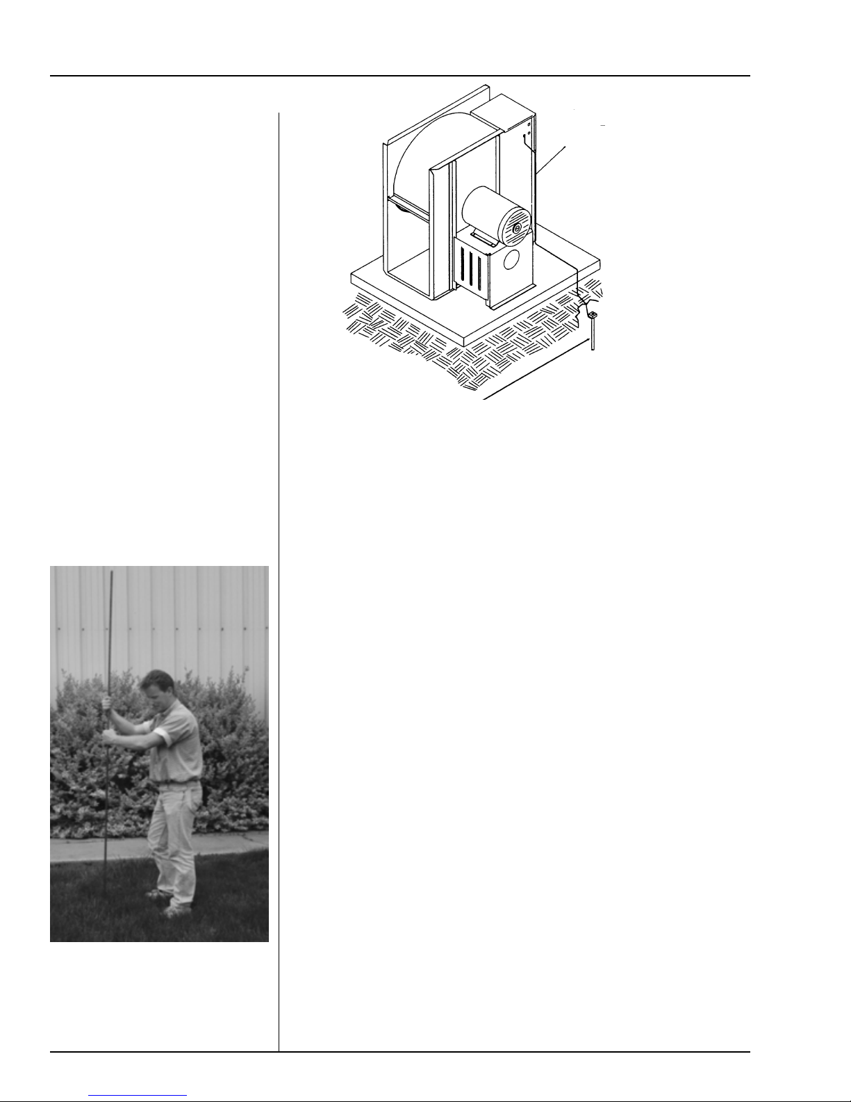
Dig a hole large enough to hold 1
or 2 gallons of water. Work the
ground rod into the earth until it is
completely in the ground.
It is recommended that previously installed units be checked to see
that a machine to earth ground has been installed by an electrician.
(Groundrodsand wires arenotsupplied by Airstream).Itisrecommended that
therodnotbedrivenintodryground.Thefollowingstepsensureproperground
rod installation:
1. Dig a hole large enough to hold 1 to 2 gallons of water.
2. Fill hole with water.
3. Insert rod through water and jab it into the ground.
4. Continue jabbing the rod up and down, the water will work its way
down the hole, making it possible to work the rod completely
into the ground. This method of installing the rod gives a good
Previously Installed Units
Proper Installation Of The Ground Rod
conductive bond with the surrounding soil.
5. Connect the bare copper ground wire to the rod with the proper
ground rod clamp.
6. Connect the bare ground wire to the fan control boxes with a
grounding lug. See figure 4.
7. Ground wire must not have any breaks or splices. Insulated
wire is not recommended for grounding.
Figure 4: Use a
#6 or approved
size bare copper
ground wire.
Install a 5/8"
diameter 8' long
copper-clad
ground rod, 2'
away from the
foundation and 1'
below the surface
of the ground or
in accordance
with local
requirements.
Autres manuels pour 2000 Series
3
Table des matières
Autres manuels GSI Group Chauffage
Manuels Chauffage populaires d'autres marques

oventrop
oventrop Regucor Series Manuel utilisateur

Blaze King
Blaze King CLARITY CL2118.IPI.1 Manuel utilisateur

ELMEKO
ELMEKO ML 150 Manuel utilisateur

BN Thermic
BN Thermic 830T Manuel utilisateur

KING
KING K Series Mode d’emploi

Empire Comfort Systems
Empire Comfort Systems RH-50-5 Guide de démarrage rapide

Empire Heating Systems
Empire Heating Systems WCC65 Manuel utilisateur

Wetekom
Wetekom 92 86 43 Manuel utilisateur

Desa
Desa SPC170-F Manuel utilisateur

Watlow
Watlow Watrod Electric Tubular Heaters Manuel utilisateur

Haverland
Haverland ECO-DRY GPS Series Manuel de la liste des pièces

Stelpro
Stelpro ASILVC2060 Series Manuel utilisateur