GS-Traq GTR-128 Manuel utilisateur

GTR-128/GTR-129
Motorcycle/ Vehicle Tracker
Quick Start Guide
GlobalSat WorldCom Corporation
16F., No. 186, Jian 1
st
Rd, Zhonghe Dist.,
New Taipei City 23553, Taiwan
Tel: 886.2.8226.3799/ Fax: 886.2.8226.3899
www.globalsat.com.tw
USGlobalSat Incorporated
14740 Yorba Court Chino, CA 91710
Tel: 888.323.8720 / Fax:
909.597.8532
www.usglobalsat.com

2
CONTENT
1. Introduction ........................................................................................................................3
1.1 Introduction...............................................................................................................3
1.2 Features .....................................................................................................................3
1.3 Hardware specification ............................................................................................4
1.4 Appearance................................................................................................................5
1.5 LED indicator .............................................................................................................5
1.6 Cab e description ......................................................................................................6
1.7 Accessories ................................................................................................................7
1.7.1 Standard Items...........................................................................................................7
1.7.2 Optional Items............................................................................................................8
2 Operation ..............................................................................................................................9
2.1 Insta the SIM card .................................................................................................9
2.2 Connect the Main Power........................................................................................10
2.3 Switch on/off Tracker.............................................................................................10
2.4 Fix the device .......................................................................................................... 11
3 Insta ation..........................................................................................................................13
3.1 Insta ing the Emergency button .........................................................................13
3.2 Connecting ignition detection ine on car ..........................................................14
3.3 Connecting Re ay....................................................................................................15
3.4 Suggested insta ation position............................................................................16

3
1. Introduction
1.1 Introduction
GTR-128/GTR-129 is designed as durable and multi-functional GPS/GSM/GPRS tracker. It
integrates highly sensitive GPS module and quad-band GSM communication module with a
powerful microcontroller that fits into a compact enclosure. The device is capable of waterproof
and ideal for use in motorcycle, golf cars and general car. It is small size and low cost for covert
and efficient tracking device. It provides real-time GPS positions anytime and anywhere with an
open view to the sky, and offers precise positioning, and reports vehicle status to the server with
necessary information shown on the map. Benefits such as enhanced fleet management,
improved vehicle safety, emergency response, are all accomplished through the implementation
of the GTR-128/GTR-129 system. The built-in GSM and GPS antennas are for easy installation
without hassle.
1.2 Features
New generation SiRF Start IV GPS module.
Compact size and Waterproof IP67 design
Built-in high sensitivity GPS/GSM antennas.
Quad-Band GSM System
Built-in motion sensor
AGPS support
Support communication protocols- SMS/TCP/UDP.
Multiple I/Os support: 1 Digital Input for custom function, 1 Digital input for optional
Emergency button, 1 Analog Input for fuel sensor, 1 Digital Output for Relay, 1 Digital Input
for ACC detection.
Over-The-Air Device Configuration and Firmware update
Alert functions including Power low/ Over speed/ Movement alarms
Tracking in preferred interval, scheduling and Geo-fence
Embedded magnet and double clips for easy installation
No any button and plug-in then power on for simple use
Multiple power kits suit to diverse vehicles and motorcycles

4
1.3 Hardware specification
Item Description
Model GTR-128 GTR-129
Dimension 61 mm X 38 mm X 19 mm
CPU High performance line ARM-base 32-bit MCU
GPS receiver SiRF Star IV high performance GPS chipset
Operation
-30℃~ + 80℃-10℃~ + 60℃
(0℃~ + 45℃for charging)
Temperature
Storage
-40℃~ + 85℃
GPS Antenna Built-in patch ceramics antenna
GSM Antenna Built-in Pi-Fa antenna
Communication Quad-Band GSM (850/900/1800/1900 MHz)
Protocol SMS/GPRS (TCP/UDP)
Power 8~36 V
Built-in Memory 32 Mb
Emergency Input Negative trigger 1
Ignition (ACC) Input Positive trigger 1
Digital Input Port Negative trigger 1
Digital Output Port Negative trigger 1 (300 mA)
Fuel sensor Input Port Analog Input 1( 0~28V), 12 bits resolution
Serial Port 115200 bps
Sensor Motion sensor
5
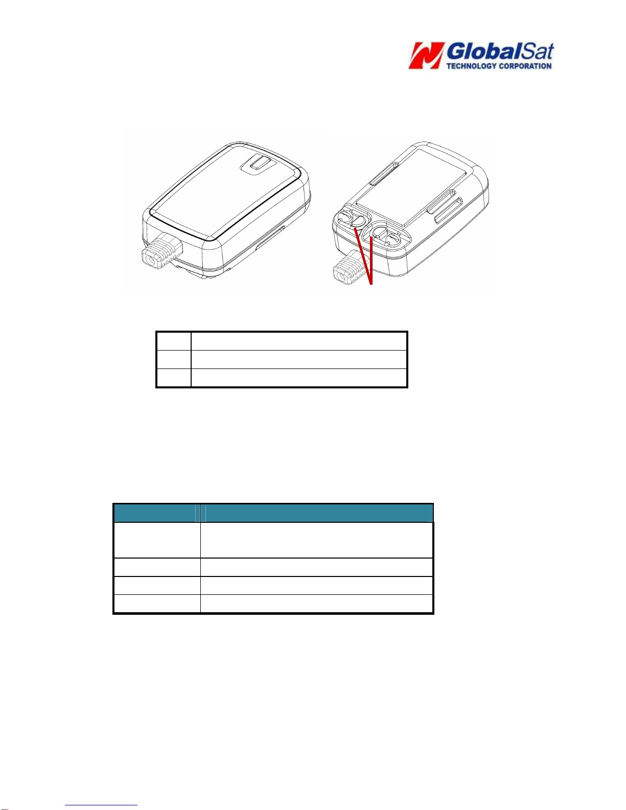
1.4 Appearance
1 LED
2 For fixing device with Velcro tape
3 Hook for screw/ unscrew back cover
1.5 LED indicator
Normal mode:
LED status
Description
Red blinking Device is being boot and SIM card not
ready
Red solid SIM card ready, but GSM not registered
Yellow solid GSM registered, but GPRS not connected
Green solid GSM registered, and GPRS connected
Hiding mode: Device would blink red light while it is being boot. After completing the boot, all
LED would go off.
1
2
2
3

6
1.6 Cable description
Wire Color Description
Green SOS (Negative Trigger)
Blue Fuel sensor input (Analog Input, 0~28 V, 12
bits resolution)
Yellow Digital Input (Negative Trigger)
Red Main Power, 9~36 V
Black Ground
White Digital Output (Negative Trigger), 300 mA
Orange Ignition Detection Input (Positive Trigger)
Black Ground

7
1.7 Accessories
1.7.1 Standard Items
Main Unit
Hardwire cable
Velcro Tape

8
1.7.2 Optional Items
Car Lighter Adaptor
External Emergency Button
OBDII Power Cable
12V/24V Relay

9
2 Operation
For first time users, please follow the steps below to complete the pre-installation.
2.1 Install the SIM card
Unscrew the cover of device. Insert SIM card with the cooper contacts face-down and the
notch on the SIM card at the right side of the SIM slot.
Note: Make sure to disable the SIM PIN entry function on the SIM card before inserting
your SIM card

10
2.2 Connect the Main Power
Connect the red wire from the cable to a power source of 9~36 V. Connect the black
wire to ground.
2.3 Switch on/off Tracker
After connecting the power, please open the back cover and adjust the power switch to On
position.
Ce manuel convient aux modèles suivants
1
Table des matières
Autres manuels GS-Traq GPS


