Grundfos CU 323 Series Manuel utilisateur

CU 323
Installation and operating instructions
GRUNDFOS INSTRUCTIONS

English (GB)
2
English (GB) Installation and operating instructions
Original installation and operating instructions
These installation and operation instructions
describe Grundfos CU 323.
Sections 1-2 give the information necessary to be
able to install the product in a safe way.
Sections 3-9 give important information about the
product, as well as information on service, fault
finding and disposal of the product.
CONTENTS
Page
1. General information
1.1 Target group
These installation and operating instructions are
intended for professional installers.
1.2 Symbols used in this document
1.2.1 Warnings against hazards involving risk of
death or personal injury
The text accompanying the three hazard symbols
DANGER, WARNING and CAUTION is structured in
the following way:
1.2.2 Other important notes
1. General information 2
1.1 Target group 2
1.2 Symbols used in this document 2
2. Installing the product 3
2.1 Location 3
2.2 Mechanical installation 3
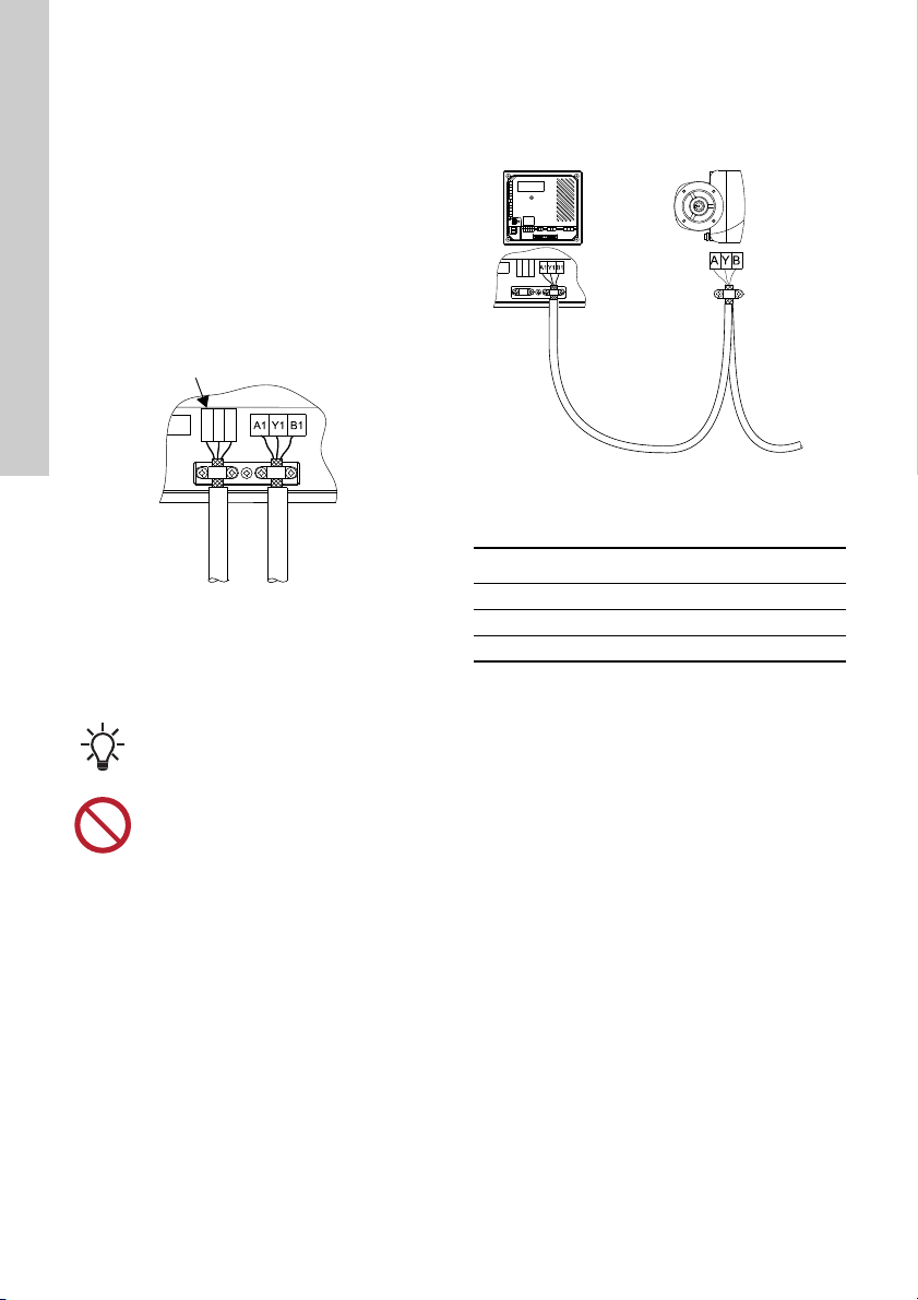
2.3 Electrical installation 4
3. Product introduction 5
3.1 Product description 5
3.2 User interface 5
3.3 Layout of the back of CU 323 8
3.4 Identification 8
4. Control functions 9
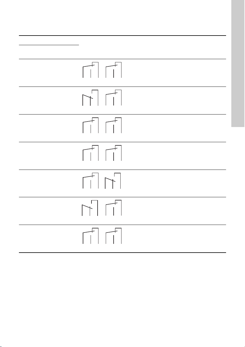
4.1 Functions of indicator lights and relays 9
5. Operating the product 10
5.1 Local mode, external stop not activated 10
5.2 Local mode, external stop activated 10
5.3 Remote-controlled, external stop not
activated 11
5.4 Remote-controlled, external stop activated 12
5.5 Adjusting the proportional pressure
setpoint 12
6. Servicing the product 13
6.1 Maintaining the product 13
6.2 Repairing the product 13
6.3 Replacing the product 13
7. Fault finding the product 14
8. Technical data 16
8.1 Operating conditions 16
8.2 Mechanical data 16
8.3 Electrical data 16
8.4 Overview of inputs and outputs 18
8.5 Dimensions 19
9. Disposing of the product 19
Read this document before installation.
Installation and operation must comply
with local regulations and accepted codes
of good practice.
DANGER
Indicates a hazardous situation which, if
not avoided, will result in death or serious
personal injury.
WARNING
Indicates a hazardous situation which, if
not avoided, could result in death or
serious personal injury.
CAUTION
Indicates a hazardous situation which, if
not avoided, could result in minor or
moderate personal injury.
SIGNAL WORD
Description of hazard
Consequence of ignoring the warning.
- Action to avoid the hazard.
A blue or grey circle with a white graphical
symbol indicates that an action must be
taken.
A red or grey circle with a diagonal bar,
possibly with a black graphical symbol,
indicates that an action must not be taken
or must be stopped.
If these instructions are not observed, it
may result in malfunction or damage to the
equipment.
Tips and advice that make the work easier.

English (GB)
3
2. Installing the product
CU 323 is only intended for factory wiring.
Before installing the product, check the following:
• CU 323 corresponds to the order.
• CU 323 is suitable for the supply voltage and
frequency at the installation site.
• CU 323 has not been damaged during
transportation.
The installation must be carried out by authorised
staff in accordance with local regulations.
Observe all safety regulations at the installation site.
Be aware that terminals L and N as well as 70 to 81
may be connected to dangerous contact voltage.
External control voltage from other groups may
occur.
2.1 Location
CU 323 is designed for indoor installation in the front
of a control panel or a separate cabinet.
For outdoor installation, mount CU 323 in a control
cabinet with an enclosure class of minimum IPX4.
2.1.1 Potentially explosive environments
CU 323 must not be installed in potentially explosive
environments, but may be used together with
Grundfos pumps approved for installation in
potentially explosive environments.
2.2 Mechanical installation
Fasten CU 323 with the four M5 x 10 screws
supplied with the product. See fig. 1 (1).
Maximum torque: 1.4 Nm.
For dimensions of CU 323, see section 9. Disposing
of the product.
Fig. 1 Mounting in panel front, standard
Connect the earth terminal between the cable
clamps on CU 323 to the mounting frame. See fig. 1
(2) and fig. 2.
Fig. 2 Earth connection
DANGER
Electric shock
Death or serious personal injury
- Switch off the power supply before you
start any work on the product. Make
sure that the power supply cannot be
accidentally switched on.
DANGER
Electric shock
Death or serious personal injury
- The installation must incorporate a main
switch.
The main switch must be placed close
to CU 323 and easily accessible for the
operator.
The switch must be marked as main
switch for CU 323.
The main switch must be according to
IEC 60947-1 and IEC 60947-3.
WARNING
Electric shock
Death or serious personal injury
- All wires to units outside the control
panel must be of the type H05VV-F
according to CENELEC HD21.
USA and Canada: All wires must
comply with the National Electrical Code
(NEC) and/or Canadian Electrical Code.
Install CU 323 in a well-ventilated location,
and do not place it close to any heat
sources.
TM03 1301 4105
Pos. Description
1 Screw (4 pcs)
2 Mounting frame
TM04 9274 3810
Min. 1.5 mm
Max. 3 mm

English (GB)
4
2.3 Electrical installation
2.3.1 EMC-correct installation
CU 323 is normally mounted in a panel which also
contains contactors and other power equipment.
To ensure faultless function, install the electronic
modules in an EMC-correct way:
• Ensure sufficient earth connection between
CU 323 and the frame. See fig. 2.
• Use screened cables for internal GENIbus.
Connect the screen to the cable clamp in front of
the terminals A1, Y1 and B1. See fig. 3.
• Use screened cables for CIM modules.
Connect the screen to the cable clamp in front of
the CIM module terminals. See fig. 3.
Fig. 3 Cable screens for external and internal
GENIbus connections fixed with cable
clamps
• Use screened signal conductors for digital and
analog inputs.
2.3.2 GENIbus connection to E-pumps
CU 323 can communicate with one or more E-pumps
via internal GENIbus.
Fig. 4 GENIbus connection to E-pumps
Connection with variable frequency drive via Modbus
(RS485):
2.3.3 Fieldbus communication interface modules
(CIM)
CU 323 can be connected to an external
communication network via an add-on fieldbus CIM
module.
A CIM module is a communication interface module.
These CIM modules are available:
• CIM 050 RS-485 GENI
• CIM 110 LON
• CIM 150 Profibus
• CIM 200 Modbus RTU
• CIM 250 GSM/GPRS
• CIM 300 BACnet MS/TP
• CIM 500 Modbus TCP, Profinet or BACnet IP.
The CIM modules must be ordered separately.
The installation of the CIM module is described in the
Hydro Multi-B service instructions available in
Grundfos Product Center. Copy the link below to see
the document online:
http://net.grundfos.com/qr/i/97916525.
TM04 9275 3810
Remove any isolating plastic tape between
the screen and the sheath before
mounting the cable in the cable clamp.
Do not twist the screen ends as this will
destroy the screening effect at high
frequencies.
Terminals for CIM module
TM04 9276 3810
GENIbus terminal Description
A Positive
YCommon
B Negative
CU 323 E-pump

English (GB)
5
3. Product introduction
3.1 Product description
The CU 323 control unit is designed for the
monitoring and control of up to four pumps.
3.2 User interface
Fig. 5 CU 323 user interface
TM04 9303 3810
1
2
3
4
5
6
7
89
10
11
12
13
14
PT
WS
On
Off
RESET
OFF AUTO
OFF AUTO
OFF AUTO
OFF AUTO
CU 323
4
3
2
1
system run
alarm
System run
Alarm
Pos. Buttons Description
1 [On/Off]: Changes the system operating mode between "Normal" and "Stop".
2 [Up]: Increases the setpoint value.
3 [Down]: Decreases the setpoint value.
4 [RESET]: Resets all alarms.
5[>]: Changes the operating mode of the individual pumps between "AUTO" and
"OFF". Each pump in the system has an Auto/Off button.
On
Off
RESET
For further information about how to
operate CU 323, see section 3.3 Layout of
the back of CU 323.

English (GB)
6
Pos. Display Description
6
"Setpoint" Shows the setpoint.
After unlocking CU 323, the setpoint will flash.
Proportional pressure control. "PPP" will be flashing for one second
followed by the current setpoint for four seconds. This function is only
available for E-pump systems.
The tank symbol appears in tank-filling mode with float switches.
or "Setpoint" Alternates between the tank symbol and the setpoint in tank-filling mode
with analog input.
External stop: Indicates that the system has been stopped externally via
a digital input.
Indicates that the system has been set to "OFF".
Indicates that the system has been set from "OFF" to "On". "On" is only
shown for three seconds after which the setpoint is shown.
Indicates that the buttons on CU 323 have been locked automatically. To
unlock the buttons, press [RESET] and arrow up or [RESET] and arrow
down simultaneously.
Indicates that the system is remotely controlled.
Local: Appears if attempts to change the local settings are made while
the system is remotely controlled.
7
"Measured value" Shows the actual, measured value on the outlet side.
Proportional setpoint at zero flow, PPS [bar]. "PPS" is visible if you press
[RESET] for four seconds. After [RESET] has been released, you can
adjust "PPS" by means of the arrow up or arrow down buttons. If the
buttons are not activated for four seconds, the system returns to normal
operation. This function is only available for E-pump systems.
Appears in tank-filling mode with float switches.
Appears in case of a primary sensor fault.
or "Measured value"
Alternates between the actual, measured value on the outlet side and
"H.L" when a maximum outlet pressure or a level limit has been
exceeded.
1___!
1___!
E.St
OFF
On
0-N
bUS
LOC
336
---
Err
H.L

English (GB)
7
* The last pump in operation might have been
stopped temporarily by the low-flow stop
function.
Pos. Indicator
light Status Description
8Off Normal state.
Red Water shortage.
9
Off Normal state.
Red Fault, primary sensor and/or redundant sensor.
The maximum outlet pressure or the level limit has been exceeded.
10 Pump LED
Off The pump has stopped due to cascade operation.
The system is in "OFF" state.
The power supply has been switched off.
Red A pump fault has occurred.
Green The pump is running.
Flashing green The pump is in standby mode or has been stopped by pressing [>]
or via remote control.
11 AUTO Yellow The pump is controlled by CU 323.
12 OFF Yellow The pump has been stopped by pressing [>] or via remote control.
WS
PT
Pos. Indicator
light
Status
DescriptionPos. 13:
"System run"
(green)
Pos. 14:
"Alarm"
(red)
13
and
14 System
LEDs
Off Off The power supply has been switched off.
On Off The system is in normal operation.*
Flashing Off The system has been set to stop.
Off On The system has been stopped due to an alarm.
On On The system is in normal operation, but there is a
warning.*
Flashing On The system has been set to stop, and there is a warning.

English (GB)
8
3.3 Layout of the back of CU 323
Fig. 6 Back of CU 323
3.4 Identification
3.4.1 Nameplate
CU 323 can be identified by means of the nameplate
on the back. See fig. 7.
Fig. 7 Nameplate
3.4.2 Type key
3.4.3 Protective earth terminal
The protective earth terminal is marked with the
symbol below. See fig. 8.
Fig. 8 Protective earth terminal
TM04 9272 3810
Pos. Description
1 Nameplate
2 Terminals for relay outputs
3 Terminals for digital outputs
4 Service connection
5 Terminals for digital inputs
6 Voltage indicator
7 Terminals for analog inputs
8 Terminals for PTC inputs
9 Terminals for CIM module, not standard
10 Cable clamps for GENIbus connection
11 Internal GENIbus connection
12 Terminals for power supply
TM04 9628 4810
Pos. Description
1 Type designation
2 Product number and version number
3 Rated voltage, frequency and power
4 Serial number
5 Production code (year, week)
Code Example CU 32 3 - 4
CU Control unit
32 Controller series
3 Model number
4 Number of pumps (2 to 4)
TM04 9739 5110
100-240 Vac 50/60 Hz - Max. 18W

English (GB)
9
4. Control functions
4.1 Functions of indicator lights and relays
System indicator lights
Operating
relay
Alarm
relay Description
"System run"
(green)
"Alarm"
(red)
Off Off The power supply has been switched off.
Permanently
on Off The system is in normal operation, and one or
several pumps are running.
Permanently
on Off The system is in normal operation, but the last
pump in operation has been stopped by the low-flow
stop function.
Flashing Off The system has been set to stop.
Off Permanently
on The system has been stopped due to an alarm.
Permanently
on Permanently
on The system is in normal operation, but there is a
warning.
Flashing Permanently
on The system has been set to stop, and there is a
warning.
CNONC
CNONC
CNONCCNONC
CNONC
CNONC
CNONC
CNONC
CNONC
CNONC
CNONC
CNONC
CNONC
CNONC

English (GB)
10
5. Operating the product
User operation depends on the system mode. The
system modes are described in the following
sections.
5.1 Local mode, external stop not activated
In this mode, the system is locally controlled, and the
external stop via digital input is not activated.
The flow charts below show examples of how
settings can be made.
Starting and stopping the system
Changing the setpoint while the system is running
Changing the setpoint while the system is in "OFF" mode
5.2 Local mode, external stop activated
In this mode, the system is locally controlled, and the
external stop via digital input is activated.
External stop via digital input has higher priority than
local control. This means that settings can be
changed locally, but they will not be effective until
external stop has been deactivated. The flow charts
below show examples of how settings can be made.
Read this document before startup.
Installation and operation must comply
with local regulations and accepted codes
of good practice.
TM04 9577 4610
OFF OFF
ON 3.5
On
Off
On
Off
Starting the system Stopping the system
TM04 9578 4610
3.5
3.6
3.4
Changing the setpoint
TM04 9579 4610
OFF 3.5
3.6
3.4
Changing the setpoint
or
Table des matières
Autres manuels Grundfos Panneau de contrôle


