Grid 1500W Manuel utilisateur

1
Grid PV-inverter
1500W/2000W/3000W/4000W/6000W
Installation and Operation Manual

2
Only an electro-skilled person or trained assembly staff can install or
open the Inverter.

3
Before you start…
Thanks for purchasing Grid PV-Inverter. GRID PV-INVERTER is a highly
reliable product due to innovative design and perfect quality control.
This manual contains important information of installation, operation and
safety reminding of this unit. Be sure to read this manual carefully before
enjoying this product.
If you encounter any problem during installing or running this unit, please
check this manual first before contacting with your local dealer or
representative. Most of the problems you encountered will be solved
according to the instruction inside.
Thank you for purchasing our product again. Please keep this manual in
safe place for later use.

4
Safety instructions
zRisk of Electric Shock
1. Do not remove the covers. No user serviceable parts inside. Refer
service to qualified service personnel.
2. Both AC and DC voltage sources are terminated inside this equipment.
Each circuit must be individually disconnected before servicing.
3. When a photovoltaic array is exposed to light, it supplies a DC voltage
to this equipment.
4. Risk of electric shock from energy stored in capacitors. Do not remove
cover until 3 hours after disconnecting all power sources.
5. This unit is designed to feed power to grid (utility) only, do not connect
this unit to AC power supplier. If connecting to those facilities, AC power
supplier will be damaged.
6. Please take out the unit from packaging box carefully. Check if there is
any outside damage. If you find any damage, please contact with your
local dealer.
WARNING: HIGH LEAKAGE CURRENT!
THE EXTERNAL PROTECTIVE EARTH (PE)-TERMINAL (SEE CHAPTER 1
“OVERVIEW”) MUST BE CONNECTED TO THE PE-CONDUCTOR
BEFORE CONNECTING SUPPLY.

5
1. Overview
3000 2000 1500
Front view Bottom view
LCD Display: Showing
the inverter status
Display
information switch
Operation LED,
Blue, Working Mode
Operation LED,
Red, fault status
Optional
communication slot:
SNMP and RS485
Input DC switch
Solar panel input
(DC)
RS232 cover
Display and connections
External protective earth (PE)-terminal
USB
AC connector

6
4000
Front view Bottom view
LCD Display: Showing
the inverter status
Display
information switch
Operation LED,
Blue, Working Mode
Operation LED,
Red, fault status
Optional
communication slot:
SNMP and RS485
Input DC switch
Solar panel input
(DC)
RS232 cover
Display and connections
External protective earth (PE)-terminal
USB
AC connector

7
6000
Front view Bottom view
LCD Display: Showing
the inverter status
Display
information switch
Operation LED,
Blue, Working Mode
Operation LED,
Red, fault status
Optional
communication slot:
SNMP and RS485
Input DC switch
Solar panel input
(DC)
RS232 cover
Display and connections
External protective earth (PE)-terminal
USB
AC connector
8
2. Installation
Before starting installation please check the following items:
zThis unit is designed for indoor and outdoor usage. But it is suggested
that the unit can’t be exposed under rain or water directly and use a
shelter to protect the unit would be better.
zDo not expose this unit to the sun directly. This may reduce the output
power due to high temperature.
zCheck the ambient temperature of installation is within specification
(-25~+55°C).
zThe grid to be connected is 230V system.
zThe connection to grid is approved by utility company .
zThe installation must be done by qualified personnel .
Though Grid PV-Inverter can be installed where temperature up to 50°C, we
still strongly recommend that it should be installed where ambient
temperature in the range of 0~40°C.
Mount Grid PV-Inverter to the wall
1. Select a wall or solid place can support the inverter.
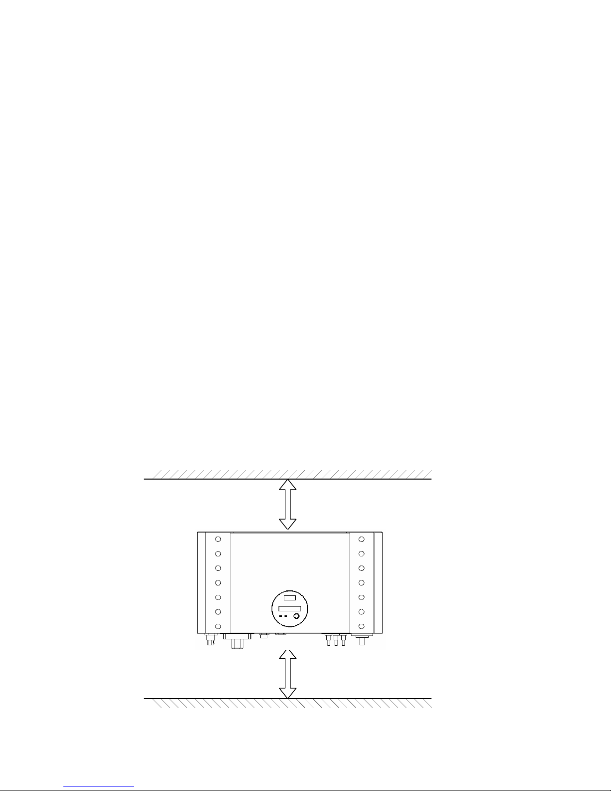
2. Convection cooling space required. To dissipate the heat generated by
inverter, 25cm space at least on the top and bottom is necessary.
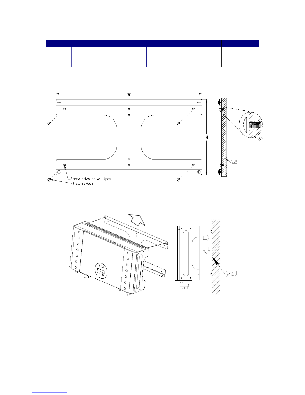
3. Mark the hole position according to following table or mounting template
attached.
25cm space
25cm space
9
1500 2000 3000 4000 6000
W (mm) 347.6 347.6 347.6 546 546
H (mm) 257 257 257 257 327
4. Drill the holes with screw.
5. Hang the inverter on the 4 screws.
6. Drive “fix screw” on bottom leg to fix the inverter.
Be sure to check the mounting of inverter. Try to lift up the inverter on the
bottom, make sure it is firmly attached.
Select the installation location carefully. The height of inverter is
recommended to be seeable, so that user can check the inverter status

10
easily; the wall must be firmly enough, this can prevent slight vibration during
inverter w
wo
or
rk
ki
in
ng
g.
.
Connect to grid (AC utility)
1. Check the grid (utility) voltage and frequency, 230VAC (or 220VAC),
50/60Hz, single phase.
2. Open the AC breaker or fuse between AC wire and utility.
3. For 4000 3000 2000 1500, connect AC wires as follows:
zDisassemble female socket.
zConnect AC wires to connection socket as indication:
z
z
zInsert Line wire to L, Neutral wire to Nand Ground wire to
Female insert
with coupling ring Shell
Pinch ring
Pressing
screw
AC wire
inserting
direction
Ce manuel convient aux modèles suivants
4
Table des matières


