
GPS Insight GO-2900 Manuel utilisateur

GO-2900 Installation Guide
Oce Locations: Oak Brook, IL • Orange, CA • Las Vegas, NV • Scottsdale, AZ (Headquarters)

Oce Locations: Oak Brook, IL • Orange, CA • Las Vegas, NV • Scottsdale, AZ (Headquarters)
Page 2
Table of Contents
Getting Started
Registration Form…………………………………………………………………...3
GO-2900 Device
Unit Overview………………………………………………………………………4
Connecting to Ground and Power………………………………………………..5-6
Connecting the Harness to the Unit…………………………………………………7
Common Installation
Installing the Antenna…………………………………………………………….…8
Connecting the Antenna Wires & Creating Tamper Evidence……………………9
Verifying Successful Installation…………………………………………………....10
Completing Registration Card……………………………………………………..11
Securing the Device……………………………………………………………….12
Appendix
Troubleshooting Light Indicators………………………………………………13-14
Frequently Asked Questions………………………………………………………15
Contact Information……………………………………………………………….16
Oce Locations: Oak Brook, IL • Orange, CA • Las Vegas, NV • Scottsdale, AZ (Headquarters)
Page 3
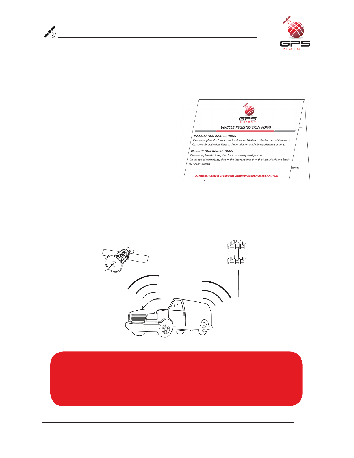
Registration Form
Fill out the enclosed registration form before completing installation.
Record the following information:
• Vehicle Identification Number (VIN)
• License Plate
• Year
• Make
• Model
• Unit’s Serial Number (10 digits)
1300915003
Installation Tip:
Metal walls and tall buildings may interfere with the reception from GPS satellites and
the cellular network. Perform installation when the vehicle is in clear view of the sky.
Conduct final installation verification after the vehicle has been running outside for
10–15 minutes.
Oce Locations: Oak Brook, IL • Orange, CA • Las Vegas, NV • Scottsdale, AZ (Headquarters)
Page 4
GO-2900 Unit Overview
The GO-2900 can be installed in light, medium and heavy vehicles. It is a GPS data
only device that does not read diagnostic data from the vehicle’s engine computer.
This device is compatible with both 12V and 24V vehicles.
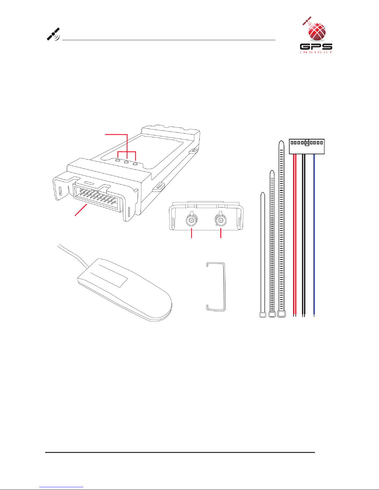
Zip Ties (X7)
Cellular PortGPS Port
Data Port
Red Blue
Black
LED Indicator Lights
Interior Glass-Mount Antenna Retainer Bar (X1)

Oce Locations: Oak Brook, IL • Orange, CA • Las Vegas, NV • Scottsdale, AZ (Headquarters)
Page 5
Connecting to Ground and Power
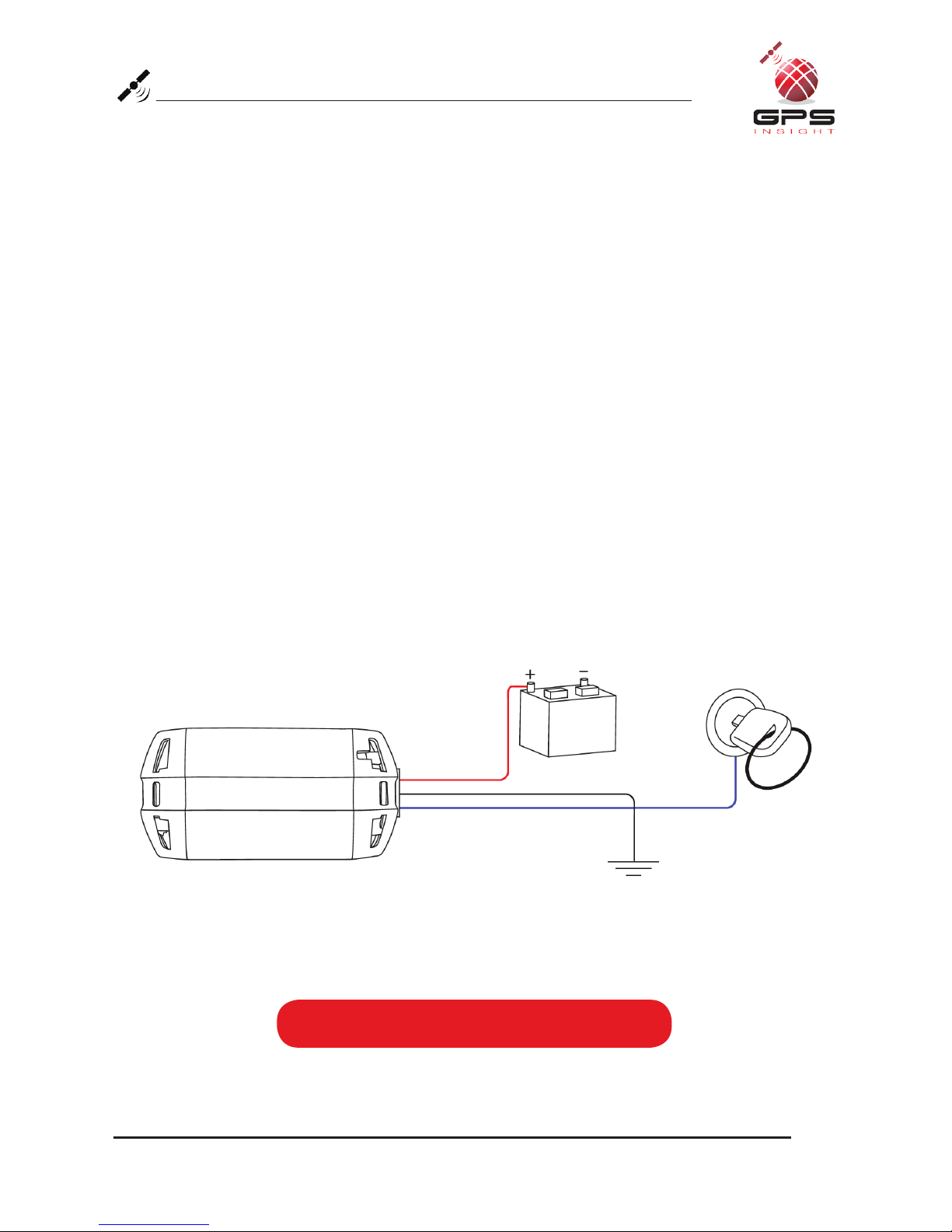
Black Wire - Ground
• With the vehicle’s engine OFF, attach the Black Wire directly to a chassis
ground point or to a ground line (chassis ground) by splicing directly to
a ground lead or by using a wire tap (recommended).
Red Wire - Continuous Power
• With the vehicle’s engine OFF, use the voltmeter to locate a 12-volt Battery
lead and attach the Red Wire by splicing directly to the lead or by using
a wire tap (recommended). If attaching to a fused lead or using an inline fuse
(not necessary), verify that it is at least 5 amps.
• Be careful not to confuse a “Retained Accessory Power (RAP)” line with a true
Continuous Power line (12 volt, always ON line).
• To determine a true Continuous Power source:
1) Ensure the Driver Door is OPEN
2) Select a wire
3) With vehicle’s engine OFF, use a voltmeter to measure the DC voltage on the
wire. It should show 12 VDC or higher.
Installation Tip:
Please ensure that the Driver Door is OPEN during the ENTIRE installation process.
Oce Locations: Oak Brook, IL • Orange, CA • Las Vegas, NV • Scottsdale, AZ (Headquarters)
Page 6
Connecting to Ground and Power
Blue Wire - Switched Power
• With the vehicle’s engine OFF, use the voltmeter to locate an IGNITION line with
switched power and attach the Blue Wire to the line by splicing directly to the
lead or by using a wire tap (recommended).
• Do NOT use an inline fuse on this line.
• Do NOT use accessory Power.
• To determine a switched power source:
1) Ensure the Driver Door is OPEN
2) Select a wire
3) With key OFF use voltmeter to measure the DC voltage on the wire - it should
show 0 VDC
4) Start the engine and confirm that the voltage of the same wire is 13.1 VDC or
higher
5) Turn the Key OFF and confirm that the voltage of the same wire is 0 VDC
To complete installation proceed to next page
3500 Unit Ground
Blue Wire
Black Wire
Red Wire
Constant Power (Battery)
Switched Power

Oce Locations: Oak Brook, IL • Orange, CA • Las Vegas, NV • Scottsdale, AZ (Headquarters)
Page 7
Connecting the Harness to the Unit
1. Connect the Harness Connector to the Dataport Interface.
2. Use Retainer Bar to secure the Harness Connector.
3. Use a zip tie to create tamper evidence. Insert the zip tie through one end of the silver
bracket and thread through the black, blue and red wires on the harness. Once the zip
tie is in place across the back of the Harness Connector, tighten and remove the excess
plastic.
Data Port
Retainer Bar
Zip Tie
Once all steps are complete,
the device will look like this.
Harness
Connector
Key
Installation Tip:
The key on the Harness Connector must be facing toward the top of the device to
properly connect.
Oce Locations: Oak Brook, IL • Orange, CA • Las Vegas, NV • Scottsdale, AZ (Headquarters)
Page 8
Installing the Antenna
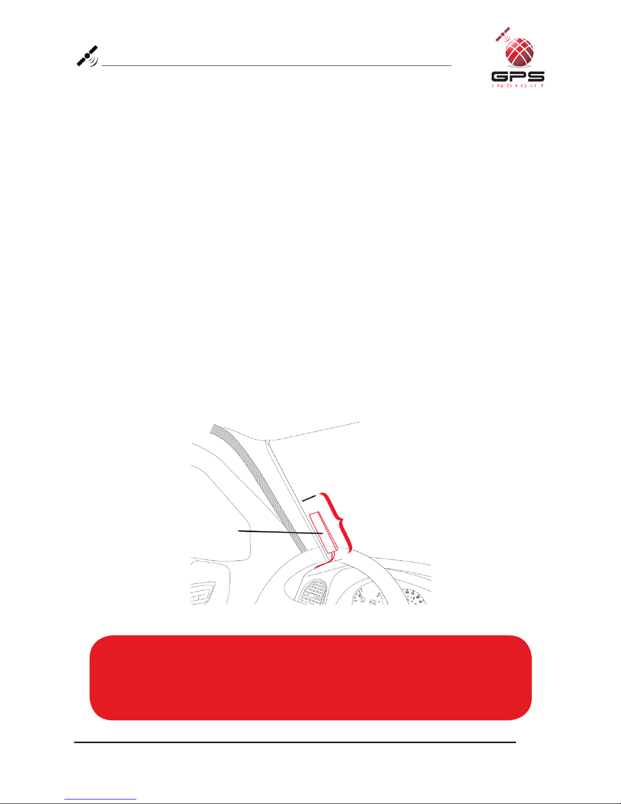
1. Use enclosed alcohol preparation pad to clean the inside windshield where the
antenna is to be placed. For proper operation, the antenna should be placed on
flat, clear glass on the driver’s side interior lower corner of the windshield.
Ensure that the antenna does not extend more than 4 ½ inches from the bottom
of the interior windshield and is located outside the area swept by the windshield
wipers.
Do NOT place the antenna in the following areas:
• Behind stickers or decals already on the glass
• On the shade band of the glass
• On a curved area of the glass
• On a moist or damp area of the glass
• On an area that will obstruct the driver’s view
2. Run the cables up the door seam or up through the dashboard.
3. Remove the protective-strip from the antenna to expose the adhesive.
4. Carefully affix the antenna to the glass that was prepped in Step 1. Press the
antenna firmly to the glass while being careful not to damage the antenna.
Installation Tip:
Please note that the ideal temperature range to perform the installation is between
70°F to 100°F (21°C to 38°C) with a minimum suggested application temperature
of 60°F (15°C).
Interior Glass-Mount
Antenna
Windshield
4 1/2 inches max
Oce Locations: Oak Brook, IL • Orange, CA • Las Vegas, NV • Scottsdale, AZ (Headquarters)
Page 9
Connecting the Antenna Wires & Creating Tamper Evidence
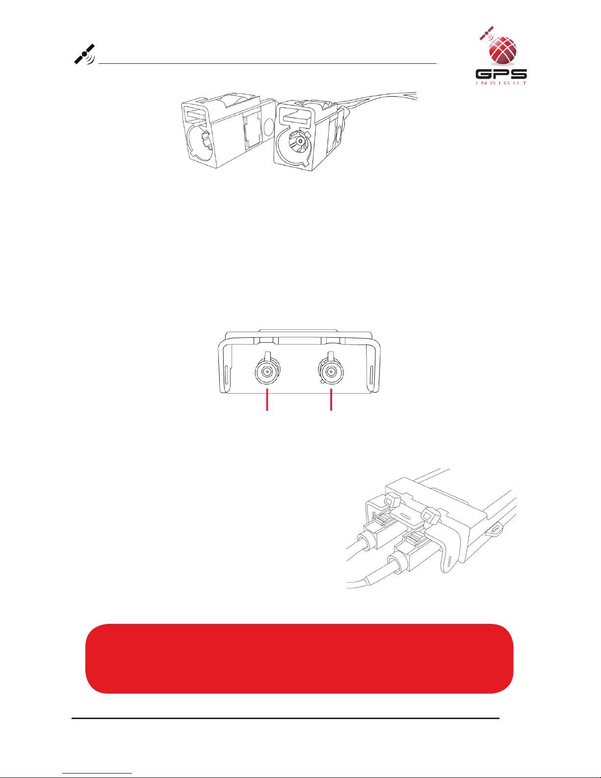
Connecting the Antenna Wires
• Each antenna wire should be plugged into the appropriate jack at the end of the unit.
Although the antennas may appear similar, please note that the Cellular antenna is
encased in a maroon end-cap and the GPS antenna is encased in blue.
• Each antenna wire should easily snap into the appropriate jack. No solder or
excessive force is necessary.
Creating Tamper Evidence
• For the GPS and Cellular antennas, slide the
end of the zip tie into the cutaway section
of the top of the device. If the antennas are
plugged in correctly, the zip tie should slide
through the top of the antennas’ plastic cap.
The zip tie should be looped through the
silver bracket of the device as well as the
plastic cap of the antenna cable. Lock the zip
tie and cut the excess plastic to prevent the
antenna cable from being unplugged.
Installation Tip:
For easier threading of the zip tie through the plastic cap of each antenna, bend the
end to curve it upward.
GPS Antenna Wire (blue) Cellular Antenna Wire (maroon)
GPS Port Cellular Port
Oce Locations: Oak Brook, IL • Orange, CA • Las Vegas, NV • Scottsdale, AZ (Headquarters)
Page 10
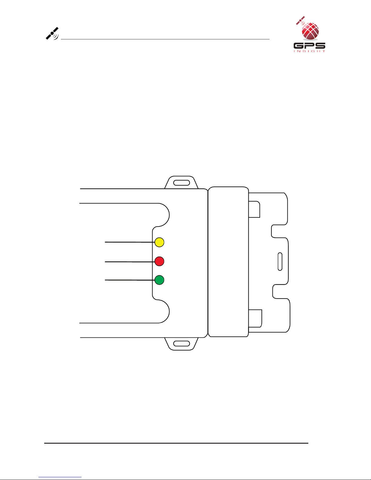
Yellow light
(Vehicle)
GO-2900 device
Red light
(Cellular)
Green light
(GPS)
Verifying Successful Installation
1. Start the vehicle’s engine. All lights (Red, Yellow, and Green) on the device
should begin blinking rapidly (twice a second).
2. The device is operating normally when the rapid blinking ceases and the Yellow and
Green lights begin to blink in a slow pattern (blinking off every 4 seconds). The Red
light pattern will continue to vary and should not be used to verify installation.
3. The vehicle must be idled or driven for at least 10 minutes to reach normal
operating mode and ensure activation is complete.
Table des matières
Autres manuels GPS Insight GPS


