Godrej SEE THRU PRO Manuel utilisateur

USER MANUAL
SEE THRU PRO
WiFi Video Door Phone
The introductory information in this document may be
changed for product improvement without prior notice.
We reserve the right of final explanation and revision.
Attend to your visitor anywhere, at anytime!
INDOOR UNIT

Table of Contents
1. Features And Functions ........................................................................2
2. Packing Contents ..................................................................................2
3. Name And Functions Of Each Part .......................................................3
3.1 Front And Rear Part .......................................................................3
4. Connection Diagram .............................................................................4
4.1 System Layout ...............................................................................4
4.2 Wiring Diagram ..............................................................................4
5. Installation .............................................................................................6
6. Operation Description ...........................................................................6
6.1 Main Screen ...................................................................................6
6.2 Visitor Call ......................................................................................7
6.3 Monitor Function ............................................................................8
6.4 Multimedia .....................................................................................8
6.4.1 Image & Video Storage .........................................................8
6.4.2 Image & Video Review ..........................................................8
6.4.3 Voicemail Function ................................................................9
6.5 Intercom Function ..........................................................................9
6.6 Wifi Function(optional) ...................................................................9
6.6.1 Add Device ............................................................................9
6.6.2 Control The Monitor By Cellphone .....................................12
6.6.3 Call Forwarding Latency ......................................................13
6.7 Setting Page ................................................................................13
7. Specifications ......................................................................................15

1
WARNING AND CAUTION
Please make sure to follow the instructions to prevent any danger or property
losses.
Warning: Death or serious injury is expected
Do not disassemble, install, or repair this product on your own accord
Do not place the product near a hot or humid place
Do not forcibly bend the cord or put a heavy object on the product
Do not use water, thinner or a detergent used to wash oil products
to wash the exterior
Do not connect to other products while in use
Make sure to clean the unit with a dry cloth to prevent any breakdown
or electric shock
If the product emits a peculiar noise, odor or smoke, immediately cut
off the power, and then contact the service center
Do not put the plug in the socket with a wet hand
Caution: An injury or property loss is expected
Make sure that dust or foreign substances does not gather on the product
Make sure to prevent foreign substances from entering the product
Avoid direct rays of the sun or heating devices at a time of installation
Install the product in a flat and stable place
Pull the plug if the product is not in use for a long time
Do not unplug the micro SD card when recording, this generally causes
loss of data

2
1. Features And Functions
Remark:
• The micro USB to RJ45 cable is only for the monitor with the WiFi function.
7” capacitive touch screen monitor,1024*600 resolution
GUI menu support sliding operation
Up to 2 door stations, 2 CCTV cameras,1 master monitor + 3 slave monitors
Built-in WiFi module can support local and remote mobile phone control (optional)
Inner flash memory and micro SD card
Auto & manual video/picture recording
Point-to-point intercom and broadcast
Selective 16 MP3 melodies
Ringtone volume & talking volume adjustable
Brightness, color and contrast adjustable
Leave voice message for visitors
Supports call forwarding function
Supports motion detection
DC power input
Multi-language
Do not disturb function
•
•
•
•
•
•
•
•
•
•
•
•
•
•
•
•
•
2. Packing Contents
Power supply
User manual
Main body Two foams
Micro USB to
RJ45 cable
4*4 pin wiring cable
Screw (KM M4* 10mm)
M4*35mm
Plastic expansion pipe
KA M4*35mm
Mounting screw
PM M3*6mm
Door Camera Hood Cover
Rubber Stopper
H2 Wrench
Wall bracket
3
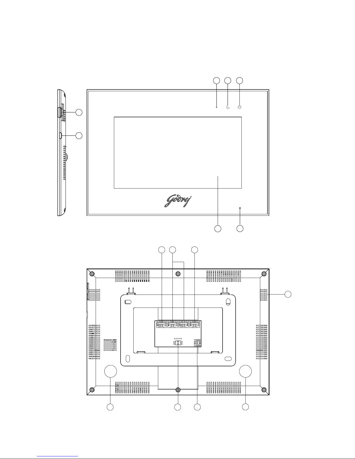
3. Name And Functions Of Each Part
3.1 Front And Rear Part
1
2
345
6
7
8 9 10
11
12
13
14
12

4
4 4 4
Master Ext 1 Ext 2 Ext 3
4
4
22222222
4. Connection Diagram
4.1 System Layout
4.2 Wiring Diagram
Please be careful to wiring on polarity.
NO. Part Name Description
1Micro SD Card Slot Socket for micro SD card
2Micro USB Slot Socket for micro USB to Rj45 (only for monitor
with WiFi)
3 Power Indicator White LED switches on when power is on
4Do-not-disturb/Leaving Mode
Indicator
Purple LED switches on when mute function is enabled /
Purple LED flashes on when leaving mode is enabled
5Message Indicator Green LED flashes when there is a new
Image / video
6Microphone Receives voice from the user
7Screen 7” digital touch screen
8CCTV Input Interface for CCTV 1 / CCTV 2
9Video Input Interface for door station 1 / door station 2
10 Intercom Interface for extension monitors
11 Speaker
12 Foam Pasting Location Protection from deformation
13 DC Power Input Connector for DC adapter
14 Switch Impedance matching for video signal

5
» Intercom wiring diagram with one monitor.
GND
VD-IN
GND
VD-IN
SYV-75-5
VIDEO2
VCC 2
GND
AUDIO2
CCTV2
GND
CCTV1
GND
GND
VCC
AD1
GND
VCC1
VD1
AD I/O
GND
DATA
VD I/O
AD2
GND
VCC2
VD2
SYV-75-5
VIDEO1
VCC 1
GND
AUDIO1
» Intercom wiring diagram with master monitor and extensions (please pay attention to the
impedance matching switch)
GND
VD-IN
GND
VD-IN
SYV-75-5
VIDEO2
VCC 2
GND
AUDIO2
CCTV2
GND
CCTV1
GND
GND
VCC
AD1
GND
VCC1
VD1
AD I/O
GND
DATA
VD I/O
AD2
GND
VCC2
VD2
SYV-75-5
VIDEO1
VCC 1
GND
AUDIO1
CCTV2
GND
CCTV1
GND
GND
VCC
AD1
GND
VCC1
VD1
AD I/O
GND
DATA
VD I/O
AD2
GND
VCC2
VD2
Master monitor
Extension 1
CCTV2
GND
CCTV1
GND
GND
VCC
AD1
GND
VCC1
VD1
AD I/O
GND
DATA
VD I/O
AD2
GND
VCC2
VD2
Extension N N≤3
ON
1 2
ON
1 2
ON
1 2
ON
1 2

6
5. Installation
»Monitor installation location
Standard monitor installation height is about 1,500mm where screen center is at eye level;
in this case, wall-hanging metal center is 1,450mm above ground level.
»Wiring and installation of indoor monitor
1) Remove mounting bracket behind monitor and fix it on the wall with screws;
2) Pull the cable out and connect the system according to 4.2 wiring diagram;
3) Hang the monitor on the mounting bracket;
4) Plug DC adapter’s power plug into the power socket.
6.1 Main Screen
Touch the screen anywhere in standby mode, the main page will be shown as follows:
6. Operation Description
It will show corresponding functions on pressing each icon on the main screen. It will also
show the main setting page when you slide the main page to the right or left.

7
When door station calls in, the visitor’s image will be shown on the monitor screen and
you can press [Talk] icon to talk with the visitor and press it again to terminate the call.
6.2 Visitor Call
※Icon Definition
capture a picture record a video
switch between door stations
and CCTV cameras talk
release the electric lock call transfer manually
adjust display
parameters (brightness/color/
contrast) and volume
back to main screen
During the talk :
• You can record a video or capture a picture from the calling door station
automatically depending on the system setting.
You can press [Change] icon to switch to another door station or CCTV camera, and
the current talk will be terminated.
You can press [Transfer] icon to transfer the current call to other extension monitors.
•
•
8
6.3 Monitor Function
When you press the [Camera] icon on the main screen, the system will enter monitor mode,
and will show image from the corresponding door station and CCTV camera.
6.4 Multimedia
6.4.1 Image & Video Storage
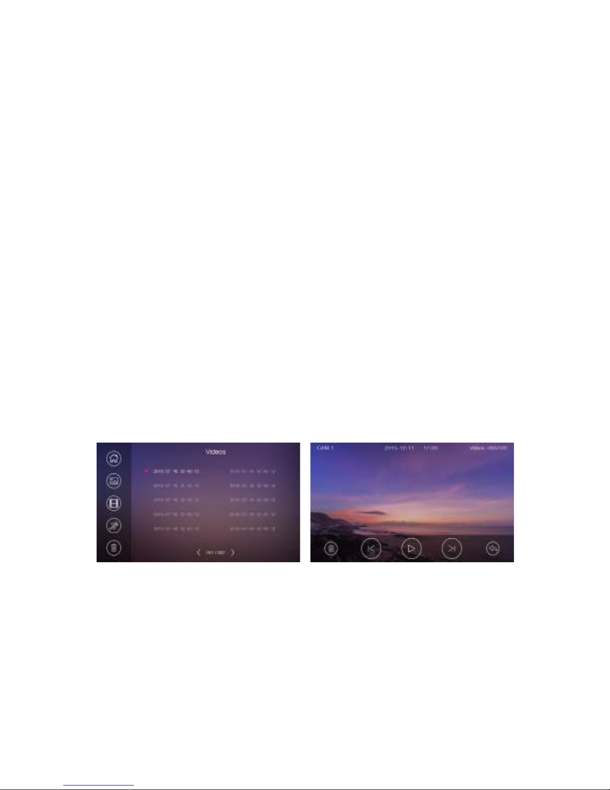
6.4.2 Image & Video Review
Press [Memory] icon on main screen, to review the image/video.The image/video list
with a red circle means that the image/video is not viewed. Press the corresponding
list directly to review the image/video.
Remark:
• The [Transfer] icon will be disabled in monitor mode.
If you insert micro SD card, the monitor can record images and videos; if you do not insert the
micro SD card, the monitor will capture only images.
Maximum Capacity: micro SD card:1000 images and 128 videos
Storage:100 images
When full, the newest image/video will automatically overwrite the oldest image/video.
Remark:
• Micro SD card must be formatted by the monitor before usage.
Micro SD card is excluded in the package.
The videos include both the video recorded during monitoring as well as during
motion detection.
•
•
Table des matières
Autres manuels Godrej Système d'interphone


