www.geosatpro.com Toll Free 888-483-4673
5
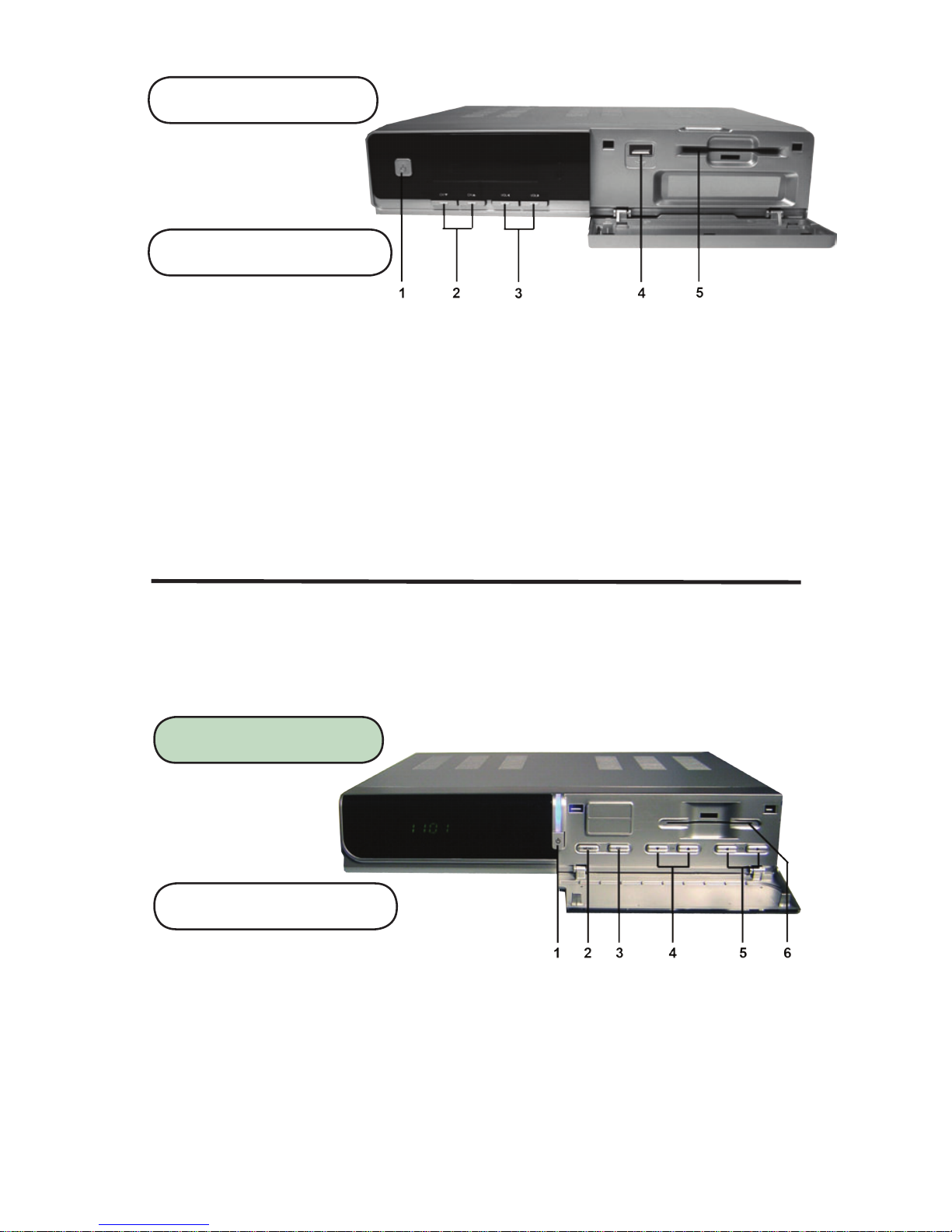
DSR200c / DVR1100c Specications
MPEG Transport Stream & AV Decoding
Transport Stream MPEG-2 ISOIIEC 13818 / Transport Stream Specification
Profile Level MPEG-2 MP@ML
Input Rate Max. 90 MbiU
Video Resolution 720 x 480 (NTSC)
Audio Decoding MPEG / Musicam Layer I & II
Audio Mode Single channel / Dual channel Joint Stereo / Stereo
Teletext VBI & OSD / Closed Captioning pass through, EIA-608 compliant
Sampling Rate 32, 44.1 and 48KHz
Conditional Access Module Interface
SMART CARD 1 SLOT, ISO 7816, GSM11.11 and EMV (payment systems) compatibility
Tuner & Channel
Input Connector F-type (Output loop-through), IEC 169-24, Female
Signal Level -25 to -65 dBm
LNB Power / Polarization Vertical: +13.5 ±5
Horizontal: +18.5Vdc ±5% Current : Max. 500mA. Overload protected
22KHz Tone Frequency: 22KHz ±2KHz
DiSEqC Control Amplitude: 0.8 ±0.2V Version 1.0, 1.1, 1.2, USALS Compatible
Demodulation QPSK
Input Symbol Rate 2-45 Ms/s Convolution Code Rate 112, 2/3, 3/4, 5/6, 7/8 with Constraint Length K=7
AV & Data Input/Output
RCA Output CVBS (Yellow), L, R Output (White, Red) w/Volume, YUV Component, S-VHS (Y/C) Video
SPDIF Dolby Digital Bitstream Out (Optical)
Data Interface RS-232, Transfer rate 115Kbps, 9 pin D-Sub Male Type
USB: USB 2.0, Type A Connector 5V 1500mA / DVR1100c - Digital Video Record Function
RF Modulator
TV Standard NTSC
RF Connector 75 Ohms, F-type, Loop - through
Frequency Range VHF - CH3, CH4
System Resources
Main Processor ARM946 RiscProcessor
Flash Memory 4 Mbyte
Program DRAM DSR200c - 16 Mbyte
DVR1100c - 32 Mbyte
Channel Capacity Digital Channel: 5,000
Front VFD Display (3 Icon, 5 digit Alphanumeric)
Power Supply
Input Voltage AC 90 to 240V, 50 - 60Hz
Power Consumption Max. 30W
Protection Separate Internal Fuse
Type SMPS
Physical Specification
Size (W x H x D) DSR200c - 260 x 50 x 210mm
DVR1100c - 290 x 50 x 220mm
Net Weight 2.0Kg