2.1.1 Hydrophones
The streamer uses Geometrics’ unique proprietary polymer hydrophones. The
hydrophone incorporates design features offering superior performance compared to
previous polymer hydrophone designs as well as the traditional PZT ceramic-type
hydrophones. Specifically, it is non-shattering and incorporates an isolating platform,
making it immune to cable-borne energy. In addition, other design aspects allow its
response to acoustic pressure alone to dominate the output.
The hydrophones are depth-limited and become inoperable at depths greater than 30 ±5
m. The inoperable state is temporary and functionality fully recovers when the depth is
reduced. This limitation allows the MicroEel to be exported under less strict US
Department of Commerce laws.
2.1.2 Hydrophone Preamplifiers
The true differential preamplifier used with the hydrophone is of a single-pole low-cut
and a single pole high-cut design. The low-cut frequency is determined by the ½πRC
time constant which is related to the element capacitance and the input resistance of the
preamplifier front-end. The preamplifier features exceptionally low noise. Nominal
element capacitance is 7.2 nF at 22 degrees C. The design also provides full voltage
regulation at each preamplifier. The voltage regulator isolates each channel from the
other which is desired when all preamplifiers share a common power bus.
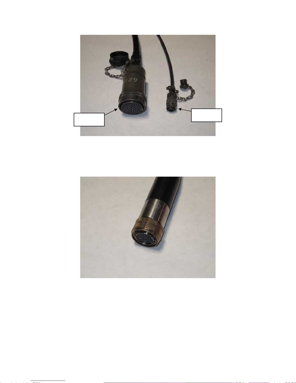
2.1.3 Deck and Tow Cable Connector Terminations
The standard topside deck cable termination is a Y-type with one 61-socket connector
(PT06J-24-61S) for analog output, and one 4-pin connector [PT06A-8-4P(SR)] for power
connection to the DHA-7/MicroEel Battery Pack (Figure 3). As an option, the analog
output termination may be ordered with a 27-socket connector(s) (NK-27-21C) instead of
the 61-socket connector. Adaptor cables are also available to connect to seismographs
with other analog input connector types.
MicroEel Solid Analog Streamer Operation Manual Page 7 of 18
Rev. C 050612 du