
Genius IPCam 350TR Manuel utilisateur

English
IPCam 350TR
Pan/Tilt Infared LED
User’s Manual
Version 1.0

English
-2-
Table of Contents
Before You Use This Product.............................................................................................. 3
Package Contents............................................................................................................... 4
Connection.......................................................................................................................... 4
Hardware Installation.......................................................................................................... 6
Software installation............................................................................................................ 8
PTCam IP Finder ........................................................................................................ 8
16-CH Recording Software....................................................................................... 10
Install the Camera behind a NAT Router...........................................................................11
Initial Access to the Network Camera...............................................................................13
Web Configuration............................................................................................................18
Main Screen with Camera View ............................................................................... 18
Definitions in Configuration............................................................................................... 21
System ...................................................................................................................... 21
Security .....................................................................................................................23
Network..................................................................................................................... 24
DDNS........................................................................................................................ 26
Stream.......................................................................................................................27
Video.........................................................................................................................28
Audio.........................................................................................................................30
Camera control ......................................................................................................... 31
Email and FTP ..........................................................................................................33
Motion Detection.......................................................................................................35
Application.................................................................................................................36
Samba.......................................................................................................................38
IP notification.............................................................................................................39
System log ................................................................................................................40
Status ........................................................................................................................41
Maintenance.............................................................................................................. 42
Appendix...........................................................................................................................43
Trouble shooting .......................................................................................................43
Technical specifications............................................................................................45

English
-3-
Symbol for Separate Collection in European Countries
This symbol indicates that this product is to be collected separately.
The following apply only to users in European countries:
zThis product is designated for separate collection at an appropriate
collection point. Do not dispose of as household waste.
zFor more information, contact the retailer or the local authorities in charge
of waste management.
Before You Use This Product
Certain regulations in your country may prohibit the use of surveillance devices. The Network
Camera is not only a high-performance web-ready camera but also can be part of a flexible
surveillance system. It is the user’s responsibility to ensure that the operation of this device is
legal before installing this unit for its intended use.
It is important to first verify that all contents received are complete according to the list in the
"Package Contents" chapter. Take notice of the warnings in “Quick installation guide” before the
Network Camera is installed, then carefully read and follow the instructions in the “Installation”
chapter to avoid damages due to faulty assembly and installation. This also ensures the product
is used properly as intended.
The Network Camera is accessible via the LAN or Internet connection. Connect your Network
Camera directly to a computer network or DSL modem, and with a standard Web browser you get
instant, on demand video streams. Within minutes you can set up the Network Camera to capture
a video sequence to a PC. Live video image can be uploaded to a website for the world to see or
made available only to select users on the network.
The Network Camera is a network device and its use should be straightforward for those who
have basic network knowledge.
The Network Camera is designed for various applications including video sharing, general
security/surveillance, etc. The “How to Use” chapter suggests ways to best utilize the Network
Camera and ensure proper operations.
Minimum System Requirement
Network Environment
LAN 10/100M Ethernet
Monitoring System Recommended for Internet Explorer
System Hardware CPU: Pentium 4, 2GHz or above
Memory Size: 128 MB (256 MB or above Recommended )
VGA card resolution: 1024 x 768 or above
System Requirement for Viewer & Recorder Application
Support OS Windows 2000 , XP, Vista
System Hardware 1-4 cameras surveillance application
CPU: Pentium 4, 2GHz or above
Memory Size: 256 MB or above
VGA card resolution: 1024 x 768 or above

English
-4-
Package Contents
If any of the above items are missing, contact your dealer immediately.
1. IPCam 350TR IP Camera
2. Software CD
3. Power adapter
4. Quick installation guide
5. Bracket
NOTE
Using a power supply with a different voltage than the one included with the Network Camera will
cause damage and void the warranty for this product.
Connection
1. DC Power Jack
The DC power input jack is located on the rear of Network Camera. The input power is 12VDC.
Use the standard power adapter included in package. Otherwise, an improper power adapter may
damage the unit and result in danger.
2. LAN Socket
Beside the DC power Jack, the LAN socket is an RJ-45 connector for connections to 10Base-T or
100Base-TX Fast Ethernet cabling. Use a Category 5 “straight through” cable to connect the
Network Camera to an Ethernet network switch or hub.
3. Microphone
The Network Camera has a built-in an internal microphone. This microphone is hidden in the
pinhole located on the head of camera.
4. Indicator LEDs
Red LED: It indicates power, red LED will turn on always after plug-in power.
Orange LED: It indicates audio; it will turn off if audio is set as mute.
Green LED: It indicates networking; it will blink every second after getting IP address.
After turning the power on, three of front LEDs will become lit, then the camera will do
self-rotation. During the self-rotation, red LED will be on and the network camera is in standby
mode for getting the IP address.
5. Infrared LEDs and Light sensor
There are six Infrared (IR) LEDs and a light sensor in front of the head of camera for night vision
purpose. The IR LEDs will auto or manual turn on when the camera is in a dark environment.
6. Factory Default Reset
This button is hidden in a pinhole on the base of the camera (see the image below). Refer to
Appendix A in this manual for more information.

English
-5-
Factory default
reset button
DC power Jack
LAN Socket
Microphone
Light sensor
Infrared LEDs
LED Indicator

English
-6-
Hardware Installation
1. Attach the Network Camera with the included stand
2. Place the Camera on the table or fix it onto ceiling or wall
Use screws to fix the Network Camera into the ceiling or a wall. You can also place the Network
Camera on the table directly.
3. Plug a RJ-45 Ethernet cable into the Network Camera
Connect an Ethernet cable to the LAN socket located on the rear of Network Camera and attach
it to the network.
4. Connect the external power supply to Network Camera
Connect the attached power adapter to the DC power jack of the Network Camera.
NOTE
Note: Use the power adapter, 12VDC, included in the package and connect it to a wall outlet for
AC power.
Attach it by
screws
Ethernet Cable
Socket

English
-7-
Once you have installed the Network Camera properly and it’s powered on, the camera will do
self-rotation and then the red LED will turn on and green LED will flash every second. It means
that the system is booting up successfully.
When factory reset is completed, the IPCam 350TR will be set to default value. The IP address
will also return to the default setting as 192.168.0.99 when DHCP is off.
DC Socket

English
-8-
Software installation
At the end of the hardware installation, the Administrator must place the product software CD into
the CD-ROM driver of the PC running in MS Windows. An auto-run program will pop up (if the
program is not on auto-run, go to the root directory of the software CD and click on autorun.exe.
PTCam IP Finder
When you installed your Network camera on your LAN environment, you may install “IP Finder”
to discover the Network camera’s IP address. The Administrator must place the product software
CD into the CD-ROM drive of the PC running in Microsoft Windows. An auto-run program will pop
up.
Click on “Install IP Finder” to run the “IP Finder” program.
NOTE
If the program is not on auto-run, go to the root directory of the software CD and click on
“autorun.exe”.
The PC’s IP address must correspond with the IPCam 350TR’s IP address in the same segment
for the two devices to communicate. Therefore, if your PC’s IP address does not correspond with
the IPCam 350TR’s IP address, you must modify your PC’s IP address.
The default settings are as follows: (DHCP off)
- Default IP – 192.168.0.99 (1~98)
- Subnet Mask – 255.255.255.0
- Default Gateway – 0.0.0.0

English
-9-
IP Finder is used to search the IP address of Network Cameras or Video servers on a LAN.
1. To set PC’s IP address in the same segment with the IPCam 350TR’s IP address.
2. Connect IPCam 350TR to a PC, then press Search to search. Video Servers or Network
Cameras will be located by the IP Finder.
3. Press “Link” to open the Web Configuration.
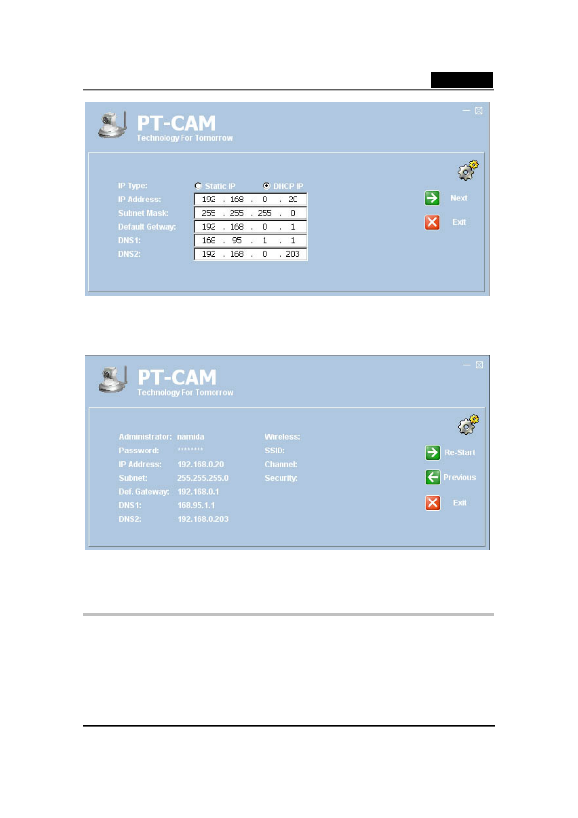
4. Or you can select any one of the Network Cameras within your LAN environment, and then
click “Wizard”, you can search out its IP address and other IP parameters as follows:
English
-10-
- Edit the IP address of this Network Camera.
- Edit the Subnet if necessary.
- Edit the Gateway if necessary.
- Edit the DNS if necessary.
- Click “Next”.
6. Make sure all the settings are correct and then click “Re-Start”, the Network Camera
will restart the system to validate the new setting after a few seconds.
16-CH Recording Software
The 16-CH recording Software of IPCam 350TR is from PowerView Soft. Refer to PowerView
Soft IP Surveillance Software User’s Manual in CD.
Table des matières
Autres manuels Genius Caméra de sécurité


