General Measure GM9907 Series Manuel utilisateur

GM9907-L5
User’s Manual
110608060003
V 0 1 . 0 2 . 0 2

©2020,Shenzhen General Measure Technology Co., Ltd. All rights
reserved.
Without Shenzhen General Measure Technology Co., Ltd.’s
permission, any company or person have no responsibility to copy,
transmit, transcribe or translate to any language version.
Our company's products are under continually improvement
and updating so we reserved the right to modify this manual at any
time without notice. For this reason, please visit our website
regularly to update newest information.
Company Website http:// www.gmweighing.com
Product Performance Standards: GB/T 7724—2008

Contents
1. Outline..........................................................................................................................- 1 -
1.1 Functions and Features....................................................................................... - 1 -
1.2 Front Panel Description...................................................................................... - 1 -
1.3 Rear Panel Description........................................................................................- 3 -
1.4 Technical Specifications.......................................................................................- 3 -
1.4.1 General specifications........................................................................................- 3 -
1.4.2 Analog part..................................................................................................- 3 -
1.4.3 Digital part.................................................................................................. - 4 -
2. Installation....................................................................................................................- 5 -
2.1 General principle................................................................................................. - 5 -
2.2 Load Cell Connection.......................................................................................... - 5 -
2.3 I/O Function Connection....................................................................................... - 5 -
2.4 Power Supply Connection..................................................................................... - 6 -
2.5 Serial Port Connection........................................................................................... - 7 -
2.6 Touch Screen Calibration.......................................................................................- 7 -
3. User Permission Description....................................................................................... - 9 -
4. Menu.......................................................................................................................... - 10 -
4.1 Recipe parameter..................................................................................................- 11 -
4.2 Weight parameter................................................................................................. - 14 -
4.3 Calibration............................................................................................................- 15 -
4.4 COM Para............................................................................................................ - 17 -
4.4.1S Continuous Send Mode.......................................................................... - 18 -
4.4.2 Response Mode-1..................................................................................... - 19 -
4.4.3Response Mode-2...................................................................................... - 21 -
4.4.4Response Mode-3...................................................................................... - 21 -
4.4.5 Printing.................................................................................................... - 22 -
4.4.6 Modbus-RTU Protocol............................................................................. - 24 -
4.4.7 Ethernet communication...........................................................................- 42 -
4.5 I/O Function......................................................................................................... - 43 -
4.5.1 Output, input port definition.................................................................- 43 -
4.5.2 IO test....................................................................................................... - 47 -
4.6 Statistics............................................................................................................... - 48 -
4.7Motor Para.............................................................................................................- 49 -
4.7.1 Motor drive feed description.................................................................... - 51 -
4.7.2 Motor drive discharge process description...............................................- 51 -

4.8 Maintenance.........................................................................................................- 52 -
5. Flowrate Function...................................................................................................... - 55 -
5.1 Real-time Flowrate...............................................................................................- 55 -
5.2 Expected Flowrate Function Description............................................................ - 56 -
5.3 Supplement Control............................................................................................. - 57 -
5.3.1 Triple supplement..................................................................................... - 57 -
5.3.2 Double supplement................................................................................... - 57 -
5.3.3 Single supplement.....................................................................................- 58 -
5.4 U disk update software........................................................................................ - 58 -
5.4.1 Upgrade steps............................................................................................- 58 -
5.4.2 Background upgrade steps........................................................................- 58 -
5.5 U disk upgrade boot interface..............................................................................- 58 -
6. Bulk ACUM process..................................................................................................- 60 -
7. Dimension(mm)......................................................................................................... - 63 -

GM9907-L5 bulk scale controller user’s manual
- 1 -
1. Outline
GM9907-L5 bulk scale controller is a weighing control instrument specially
developed for discontinuous automatic accumulation scale. The controller adopts a full
English touchscreen display interface, has the characteristics of moderate size, high
precision, powerful function and simple and practical operation.It can be widely used in
chemical industry, grain, port and other industries that need bulk metering equipment.
1.1 Functions and Features
Full English touchscreen display interface, make the operation more intuitive and
simple
28 I/O Function input and output control (12 in /16 out); input and output port
location can be customized.
I/O Function test function,convenient controller debugging
20 recipes can be stored for different weighing capacity,convenient for different
range of material packaging.
Convenient USB port to input and output of historical data.
Fill control functions, convenient bulk scale with the front filling device of control
connection.
Multiple digital filtering function
Automatic zero tracking function
Time / date function
3 level user permission setting
Dual serial ports to connect with printer, computer, Secondary display.
Single ethernet communication function, easy to communicate with the upper
computer
1.2 Front Panel Description
GM9907-L5 bulk scale controller user’s manual
- 2 -
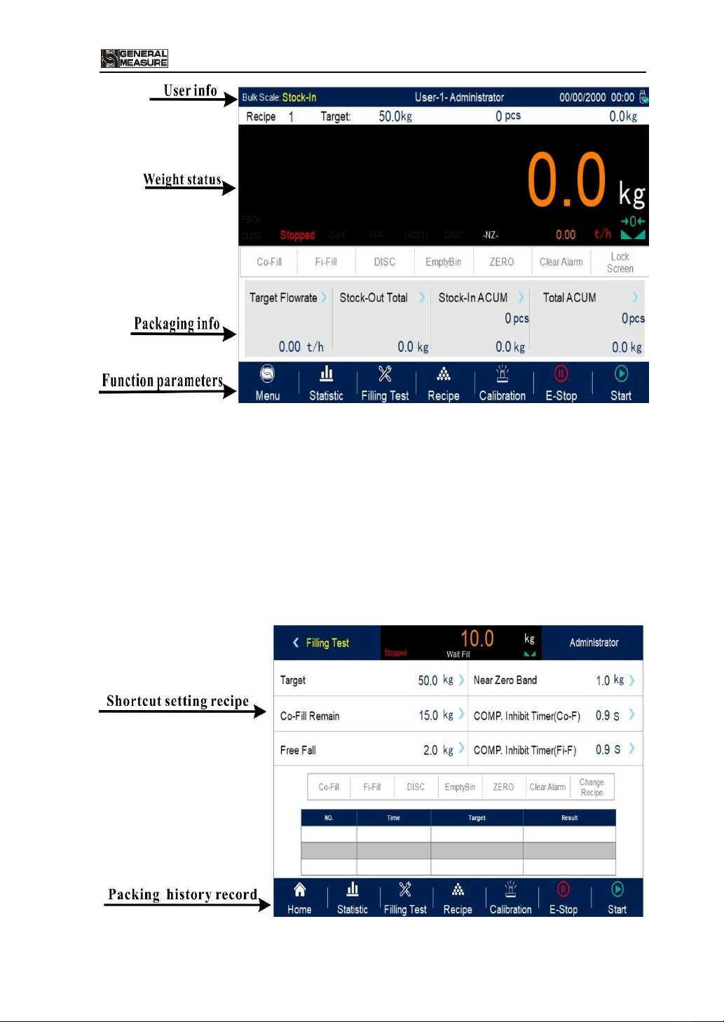
Interface Description:
User info: Show user ID, system time, recipe ID, target value, total ACUM and batch.
Weight status: Weight value display, weight unit display, Status display and shortcut
I/O Function.
Packaging info:Display current target flowrate, total stock in and out volume and
ACUM data etc.
Function parameters:Controller menu parameter and setting.

GM9907-L5 bulk scale controller user’s manual
- 3 -
Debug interface description:
Shortcut setting recipe paremeter: Can promptly setting recipe parameter, debug
controller easliy.
Packing history record: Can view the current packaging history data directly, easy
to compare.
1.3 Rear Panel Description
1.4 Technical Specifications
1.4.1 General specifications
Power supply:DC2 4V
Power filter: Included
Operating temperature:-10 ~4 0 ℃
Maximum humidity: 90% RH without dew
Power consumption: about 15 W
Dimensions::190mm ×124mm ×48mm
1.4.2 Analog part
Load cell power supply:DC 5 V 1 25 m A (MA X )

GM9907-L5 bulk scale controller user’s manual
- 4 -
Input impedance:10 M Ω
Zero adjustment range:0 .00 2 ~15 .6 25 m V (when load cell is 3mV/V)
Input sensitivity:0 . 0 2 u V / d
Input range:0 . 0 0 2 ~1 5 . 6 2 5 m V
Conversion:S igm a - Del ta
A/D Conversion rate:12 0 、24 0 、48 0 、960 Times/second
Non-linear:0.01% F.S
Gain drift:10PPM/℃
The maximum display accuracy:1/100000
1.4.3 Digital part
Display: 7-inch resistance touch screen
Negative display: "—"
Overload Indication:"Over Capacity / Loadcell Input Under"
Decimal point position: 5 options

GM9907-L5 bulk scale controller user’s manual
- 5 -
2. Installation
2.1 General principle
1)Make appropriate installation holes on the control box, ( size: 179(±1)mm ×113(±1)
mm)
2)Install the GM9907-L5 into a control box
3)Remove the fixing plates on both sides of GM9907-L5, fix it with the fixing plates and
lock them with M3*10 screws.
2.2 Load Cell Connection
GM 9907- L 5 bulk scale controller can connect resistance strain bridge sensor.
When chose the six-wired load cells, must bridge the SN+ with EX+ and bridge the SN-
with EX-
EX+:Excitation+ EX-:Excitation- SN+:Sense+ SN-:Sense- SIG+:Signal+ SIG-:Signal-
2.3 I/O Function Connection
GM 9907- L 5 bulk scale controller controls 28 lines I/O (12 input and 16 output).
It uses optoelectronic isolation technology to transfer data. The I/O signal input is low level
effective, and the output is open-collector mode. The driving current can reach 500mA and
the full load current is up to 3A, and Terminal connection is shown as below:

GM9907-L5 bulk scale controller user’s manual
- 6 -
I/O Function Input port diagram
I/O Function output connection diagram
I/O Function value of GM9 9 0 7-L5 is user-defined to facilitate wiring and some
special applications. Please refer to section 4.5
2.4 Power Supply Connection
GM9907- L 5 bulk scale controller use 24V DC power supply. The connection is
shown in the figure below:
Power terminal diagram
24V+ connect DC+,24V-connect DC-.
Note:this product use 24V DC power
supply,use 220V AC power supply will
permanently damage the controller and
cause danger.
Ce manuel convient aux modèles suivants
1
Table des matières
Autres manuels General Measure Contrôleurs


