GEA Bock HGX2 CO2 T Series Guide de configuration

Repair instruction electric motor
Series: HGX2 CO2T, HGX34 CO2T, HGX46 CO2T
HGX34 CO2THGX2 CO2T
09430-08.2016-Gb
Translation of the original instructions

09430-08.2016-Gb
2
Contents
1 Liability and Warranty ......................................................................................................................2
2 Additional Safety Information............................................................................................................2
3 Disassembly .......................................................................................................................................4
4 Assembly ..........................................................................................................................................10
1 Liability and Warranty
Liability and the manufacturer‘s warranty are excluded if
• Alterations and functional modications have been carried out,
• no original replacement parts have been used.
2 Safety Information
Target group for this repair information
¾Work on the compressor may only be carried out by persons whose technical training, skills and
experience along with their knowledge of pertinent regulations and documentation means that
they are capable of assessing the work to be carried out and detecting any possible dangers.
¾A specialist can mean a refrigeration technician for example. Note that electrical work may only
be carried our by a qualied electrician. Alternatively, on a country-specic basis, persons who
have undergone electrotechnical instruction and who have proof of their qualication are also
permitted to carry out the work.
• DANGER! This symbol refers to instructions for avoiding direct severe
dangers to persons or plant by electrical current.
• DANGER! This symbol refers to instructions for avoiding direct severe
dangers to persons.
• WARNING! This symbol is used to indicate that inaccurate compliance or
total failure to comply with the instructions could cause injury to persons or
damage to the compressor or refrigerating machine.
• This symbol is used to indicate that parts with refrigeration oils (for oil types see
compressor name plate) should be moistened prior to installing.
• This symbol indicates the permitted tightening torque for the screw.
60 Nm
• INFO! Important information or tips on simplifying work.

09430-08.2016-Gb
3
Safety Information
Important prerequisites
DANGER
Risk of electric shock.
XBefore you carry out any repair work, disconnect the compressor from the electricity network.
XTurn the main switch to „O“ (OFF).
XSecure the main switch against an unauthorised restart.
WARNING
The heavy weight of the compressor can be potentially dangerous.
Use all the seals included in the kit.

09430-08.2016-Gb
4
Disassembly
3 Disassembly
WARNING
Ensure that the compressor is depressurised before starting work.
3.1 Draining the oil
NOTE
Do not dispose of oil in domestic waste.
XDispose of the old oil in accordance with the environmental regulations and observe national regulations
¾Remove the screw plug (M22, AF19) and the seal ring.
HGX34 CO2T / HGX46 CO2THGX2 CO2T
¾Remove the screw plug (M26, AF24) and the seal ring.
09430-08.2016-Gb
5
Disassembly
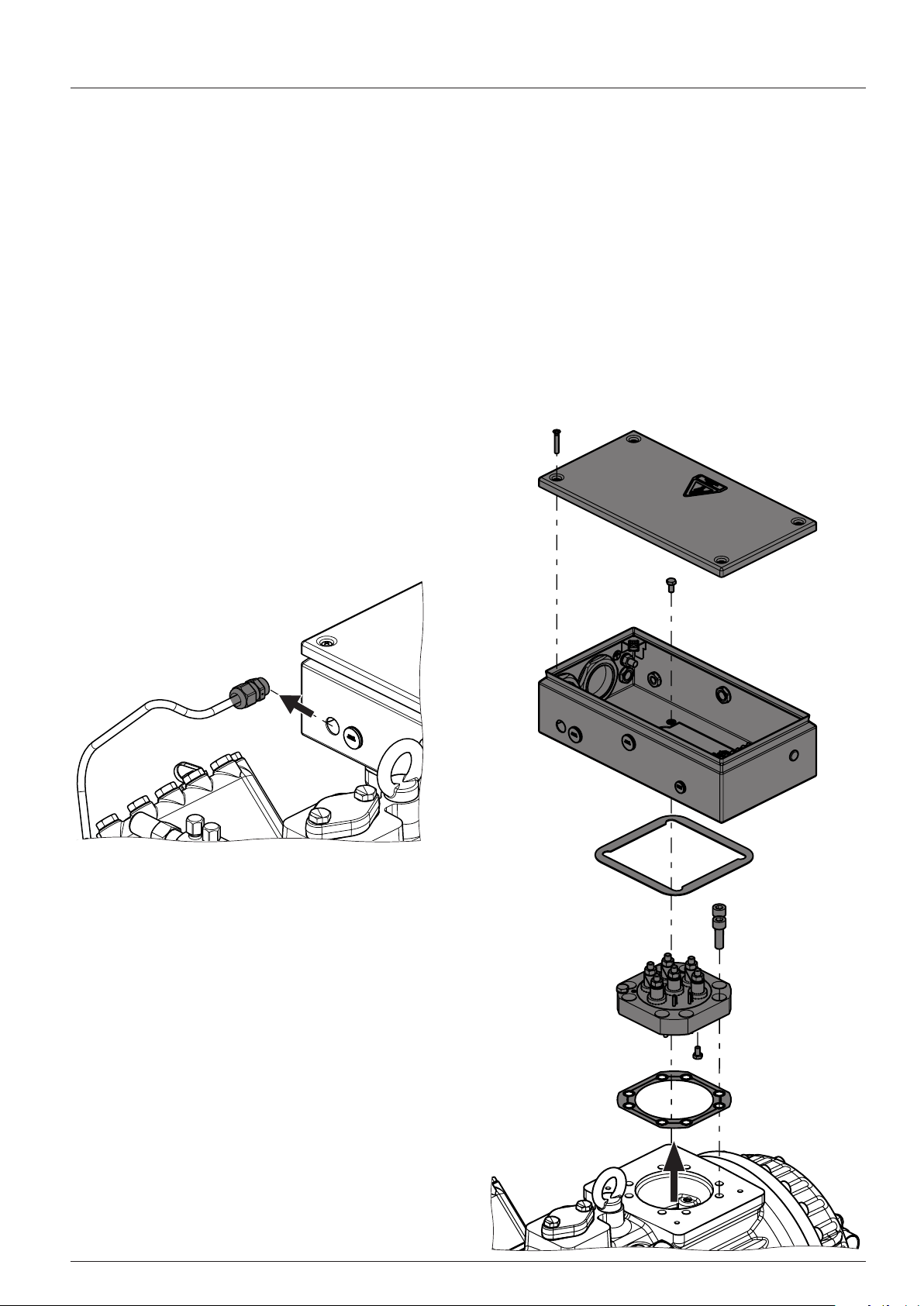
3.2 Disconnecting the electrical connections and the components
XDo not damage any cables and components.
Damaged parts must be repaired or replaced immediately.
¾Remove the connection of the oil sump heater at the terminal box, the oil sump heater can remain in the compressor
housing.
¾Remove the terminal box cover (4 hexagon head screws, if available).
¾Loosen the electrical connections on the terminal board and on the motor protection device.
¾Remove the terminal box (4 hexagon head screws M6, AF10).
¾Remove the terminal board (8 cylinder head screws M10, AF8).
¾Remove the electrical lines from the underside of the terminal board (6 hexagon head screws M6, AF10).

09430-08.2016-Gb
6
3.3 Disassemble the motor cover
WARNING
The heavy weight of the compressor and parts can potentially be dangerous;
risk of falling, danger of crushing.
XATTENTION! The residual oil ows out when the motor cover is removed.
XLay an absorbent material under the area and dispose of it in accordance with the environmental regulations.
HGX2 CO2T
¾Loosen the hexagon head screws (M12, AF19).
¾Remove the motor cover with the seal ring.
Disassembly

09430-08.2016-Gb
7
HGX34 CO2T / HGX46 CO2T
¾Loosen the cylinder head screws (M12, AF10).
¾Remove both grub screws (M10).
¾The motor cover must be pushed off the compressor housing.
For this purpose, screw two suitable screws (M10) evenly into both threads on the opposite side in order to squeeze off
the motor cover. The at gasket is destroyed in the process!
¾Take off the motor cover with the seal and the O-ring.
XCarefully clean the sealing surface from old at gasket material.
Disassembly

09430-08.2016-Gb
8
3.4 Disassemble the stator
WARNUNG
The heavy weight of the stator can potentially be dangerous; risk of falling, danger of crushing.
XUse a suitable hoist for the removal.
XTake the measures required to safely remove the stator, by screwing two round rods of the correct height
in two holes opposite one another of the motor housing.
Prevent inadvertent rolling of the removed stator.
¾Carefully pull the stator out of the compressor housing and pay attention to the cable!
¾Loosen the threaded pin of the stator protection (M8, AF4).
¾The threaded pin is glued in. For easier disassembly, warm up the threaded pin with an hot air blower.
XProtect the electrical lines from heat!
max.
75kg
Disassembly

09430-08.2016-Gb
9
3.5 Disassemble the rotor
Disassembly
¾Loosen the rotor srew (M12, AF19).
¾Pull off rotor from crankshaft. In case of stiffness, use take-off device.

09430-08.2016-Gb
10
4 Assembly
We recommend cleaning the inside of the case before the installation.
There must not be any particles and dirt in the compressor.
To assemble, reverse the order of the steps. Note any particular features such as observance of different torques.
4.1 Connecting the stator to the motor housing
¾Align the stator so that the cable harness is positioned upwards and the feather key is aligned with the groove of the
stator.
XDo not damage any cables and components.
WARNING
The heavy weight of the stator can potentially be dangerous; risk of falling, danger of crushing.
XUse a suitable hoist for the removal.
XNote the direction of the feather key — stator.
You must align the parts in order to install them.
¾Assembly instructions for HGX46 CO2 T up to design key A053, see page 13.
Assembly
Autres manuels pour Bock HGX2 CO2 T Series
2
Ce manuel convient aux modèles suivants
2
Table des matières
Autres manuels GEA Moteur


