GE WSXH208T Comment utiliser


1
CONTENTS
FEATURES .................................................................................................................................................. 2
TECHNICAL SPECIFICATIONS .................................................................................................................. 3
TORQUE REQUIREMENT TABLE .............................................................................................................. 4
RESISTANCE TABLE ................................................................................................................................. 5
SCHEMATIC DIAGRAM .............................................................................................................................. 6
TIMER CYCLE CHART................................................................................................................................ 7
ELECTRONIC SPEED CONTROLLER ....................................................................................................... 8
WIRING DIAGRAM ...................................................................................................................................... 9
TROUBLESHOOTING DIAGRAMS............................................................................................................. 10
CONSTRUCTION AND OPERATION.......................................................................................................... 16
FUNCTIONAL COMPONENTS AND PARTS .............................................................................................. 21
Top Panel ..................................................................................................................................................... 21
Service Panel ............................................................................................................................................... 21
Loading Door ................................................................................................................................................ 21
Door Strike ................................................................................................................................................... 21
Door Hinge ................................................................................................................................................... 22
Door Safety Switch Assembly (Door Lock) ................................................................................................... 22
Timer ............................................................................................................................................................ 22
Timer Diagnostic Aid .................................................................................................................................... 24
Water Level Control ...................................................................................................................................... 26
Water Temperature Selector Control ............................................................................................................ 26
End of Cycle Signal ...................................................................................................................................... 27
Extra Rinse Switch ....................................................................................................................................... 27
Water Inlet Valve .......................................................................................................................................... 27
Automatic Dispenser .................................................................................................................................... 29
Drive Motor ................................................................................................................................................... 31
Drive Belt ...................................................................................................................................................... 32
Electronic Speed Control .............................................................................................................................. 33
Drain Pump and Motor Assembly ................................................................................................................. 34
Air Bell and Pressure Connecting Tube ........................................................................................................ 34
Tub Counterweights ..................................................................................................................................... 35
Air Shock Absorber....................................................................................................................................... 36
Door Bellows ................................................................................................................................................ 36
Outer Tub ..................................................................................................................................................... 36
Inner Tub and Bearings ................................................................................................................................ 37
Tub Vanes .................................................................................................................................................... 38
Exploded Views ............................................................................................................................................ 39
Timer Diagnostic Aid .................................................................................................................................... 42
Thisservicemanualis intended for use by persons having electrical and mechnical training and a level
of knowledge of these subjects generally considered acceptable in the appliance repair trade. The
manufacturer cannot be responsible, nor assume any liability, for injury or damage of any kind arising
from the use of this manual.
WARNING
RETURN MAIN MENU

2
FEATURES
PLASTIC OUTER TUB - The two piece outer tub is formed from tough, lightweight polypropylene.
STAINLESS STEEL TUB - The wash tub, which has a 25 year warranty, is constructed of durable stainless
steel .
DISPENSER DRAWER - The dispenser drawer will add diluted detergent, bleach, and fabric softener at the
correct time during the wash or rinse cycles.
SUSPENSION SPRINGS - The tub assembly is supported from the mid-section by two suspension springs
which limit vibration to the outer cabinet.
AIR SHOCKS - Two air shocks dampen tub vibration during out of balance conditions.
FRONT MOUNTED TIMER - The timer is mounted to the front control panel. The timer knob contains an
adjustment feature to calibrate the indicator mark.
MOTOR SPEED CONTROLLER LOCATION - The motor speed controller is mounted to the right rear
corner of the base where it is protected from damage.
DOOR LOCK PTC - The PTC keeps the door locked during spin and tub coast down.
REPLACEABLE SIDE PANELS - Side panels are replaceable, but are riveted to base and front panel for
additional strength and rigidity.
FIXED FRONT PANEL - The front (upper) panel is riveted to the side panels for maximum cabinet strength
and rigidity.

3
MODEL SPECIFICATIONS WSXH208T0WB
Cycles
Regular
Agitate (in seconds) 13.3
Pause (in seconds) 3.3
Delicate
Agitate (in seconds) 3.3
Pause (in seconds) 13.3
Electronic Speed Control yes
(Operational Speeds)
Wash Speed 52 RPM
Spin Speed - slow 450 RPM
Spin Speed - fast 850 RPM
Drain Pump Motor (Detached 120 VAC Motor)
Pump Out Height Maximum (inches) 96
Drain Hose Length to Pump (Inches) 60
Pump Out Time 60 sec. max.
Pump Speed - RPM 2550
Pump Output
@ 3 ft. 13.0 GPM
@ 6 ft. 10.0 GPM
@ 8 ft. 8.0 GPM
Drive Motor (16 Pole Universal DC Motor)
Drive Belt (Poly-V, 6 rib) yes
Pulley Ratio (Pulley to Motor RPM) 1 to 16
Water Supply
Water Pressure - Maximum (PSI) 120
Water Pressure - Minimum (PSI) 15
Total Water Usage (max. gallons approx.) 25
Water Level (no load - measured from bottom of spin drum) 4-5/8" ± 3/8"
Electrical Data
Drive Motor (16 Pole DC Type Motor)
Volts (120, 60 Hz.) 15 amp yes
Wash R.P.M. 832
Spin R.P.M. 10400
Wattage
Agitate (with 10 pound clothes load) 370 max.
Spin (with 10 pound clothes load) 850 max.
Plumbing Requirements
Drain 1-1/2" Standpipe (minimum height 24") yes
Water Supply - Separate Hot & Cold Faucets yes
(3/4", 11-1/2 threads per inch)
Capacity (Inner Tub)
Cubic feet 2.65
Max clothes load 14 lbs.
Dimensions (Inches Minimum)
Height 34-5/8
Width 26-7/8
Depth 27 1/4
TECHNICAL SPECIFICATIONS
4
TORQUE REQUIREMENT TABLE
TORQUE REQUIREMENT TABLE
DESCRIPTION TORQUE
Buzzer Mounting 25 - 35 in. lbs.
Counterweight to Tub 60 - 75 in. lbs.
Door Hinge to Cabinet 30 - 45 in. lbs.
Door Hinge to Door 25 - 35 in. lbs.
Door Latch 10 - 15 in. lbs.
Door Lock Switch 15 - 25 in. lbs.
Door Frame Assembly
Screws 10 - 15 in. lbs.
Drain Pump to Pump
Bracket 25 - 35 in. lbs.
Tub Support to Tub 24 ft. lbs.
Extra Rinse Switch 24 - 35 in. lbs.
Motor to Tub 25 - 35 in. lbs.
Outer Tub Halves (front to
rear) 70 - 85 in. lbs.
Pressure Switch
Mounting 15 - 20 in. lbs.
Tub Pulley to Shaft 310 - 350 in. lbs.
Timer Mounting 20 - 40 in. lbs.
Water Temperature
Switch 15 - 20 in. lbs.
Water Valve Mounting 25 - 35 in. lbs.

5
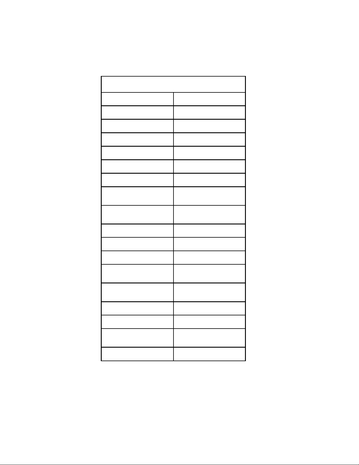
RESISTANCE TABLE
RESISTANCE TABLE
Resistance Ohm value +10% @ 770F (250C)
Door Lock Solenoid 380
Drive Motor
Stator Winding
(Tapped Field)
Stator Winding (Full
Field)
Tachogenerator
Motor Thermal
Protector
Armature (Rotor)
0.37
1.26
135
less than 1
less than 5
Pump Motor 4.6
Timer Motor 2070
Water Valve
Solenoids 880
6
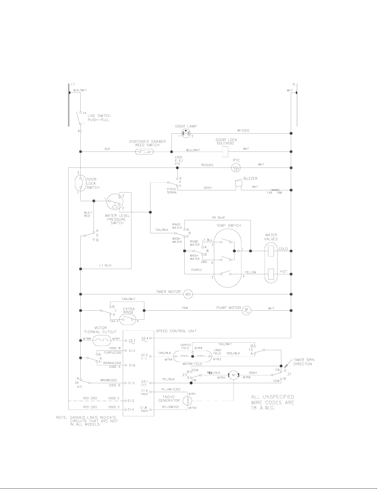
SCHEMATIC DIAGRAM

7
TIMER CYCLE CHART
8
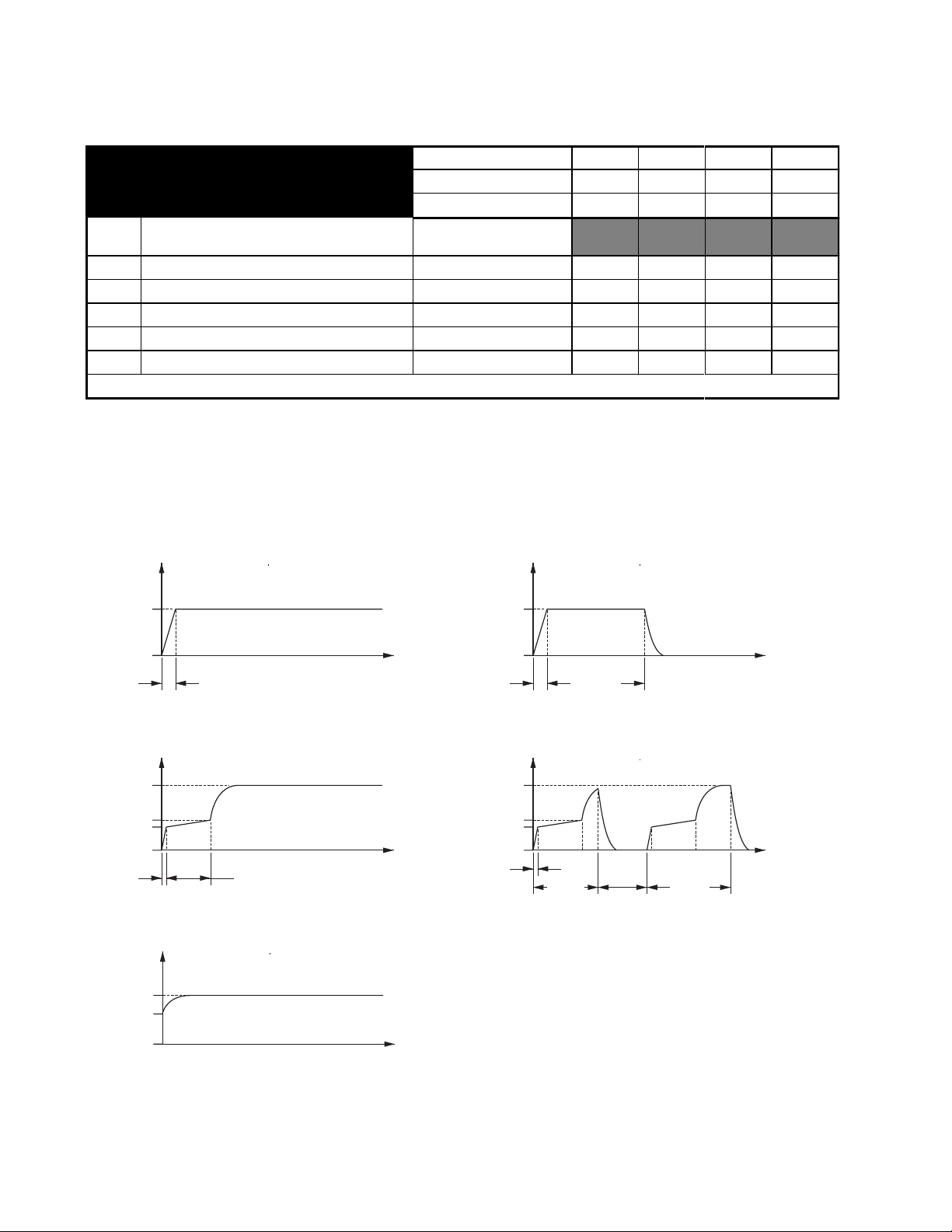
ELECTRONIC SPEED CONTROLLER
MOTOR MOVEMENT
1 Sec.Max.
1 Sec.
Max.
1 Sec.
Max. 1 Sec.
Max.
1 Sec.
Max.
1 Sec
Max.
1 Sec
Max.
42 42
20 ± 1 27.00 26.67
90 90
450 450
650
450
0
0 0
0 0
52
3.3 Sec
t (sec)
t (sec)
t (sec)
t (sec)
DRUM RPM
DRUM RPM
- NORMAL (N) WASH PHASE
- SPIN 1 (S1) PHASE
- DELICATE (D) WASH PHASE
- INTERVAL SPIN (S1+ S1) PHASE
- SPIN 2 (S2) PHASE
DRUM RPM
DRUM RPM
DRUM RPM
37.00
52
t (sec)
SPEED CONTROL
OPERATION
CONNECTOR NUMBER C1 .2 C1 . 3 C1 . 5 C1 . 6
SPEED CONTROL CODE E D B A
TIMER CONTACT 4 B 24 B 9 B 9 A
DRUM
RPM TUB OPERATION MOTOR MOVEMENT (See
Below)
52 AGITATE - CONTINUOUS (NORMAL) N 0 1 0 1
52 AGITATE - DELICATE (& DRAIN) CYCLE D 0 1 1 0
450 SPIN - CONTINUOUS S1 1 X 0 0
450 INTERVAL SPIN S1+S1 1 X 0 1
650 SPIN - CONTINUOUS S2 1 X 1 0
1 = 120 VAC, 0 = 0 VAC, X = DON’T CARE
850
850
9
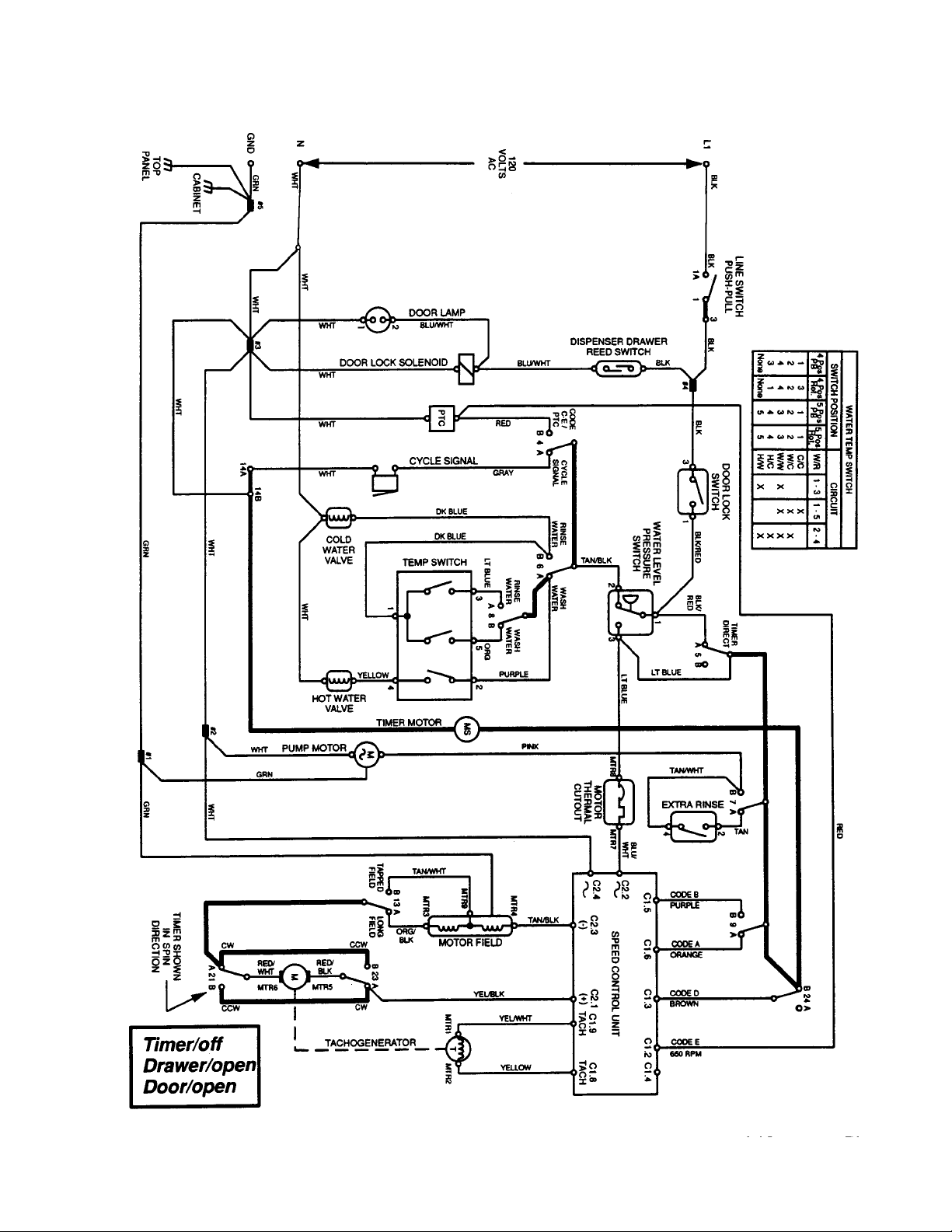
WIRING DIAGRAM
Table des matières
Autres manuels GE Rondelle

GE
GE Profile WPRB8050 Manuel utilisateur

GE
GE G161 Manuel utilisateur

GE
GE G158 Manuel utilisateur

GE
GE WWA8849R Manuel utilisateur

GE
GE WNSE5699 Manuel utilisateur

GE
GE WSLS1500 Instructions originales

GE
GE GTWN2800DWW Manuel utilisateur

GE
GE GTW465 Manuel utilisateur

GE
GE G005 Manuel utilisateur

GE
GE PTWN8050M0WW and Mode d'emploi

GE
GE Spacemaker WSXH208 Instructions originales

GE
GE G008 Manuel utilisateur

GE
GE WCRD2050DWC Manuel utilisateur

GE
GE GTWN2800D0WW Manuel utilisateur

GE
GE G161 Manuel utilisateur

GE
GE Profile WPGT9350 Comment utiliser

GE
GE Spacemaker WSM2780 Manuel utilisateur

GE
GE GTW490 Instructions originales

GE
GE WWA3100B Manuel utilisateur

GE
GE G011 Manuel utilisateur


