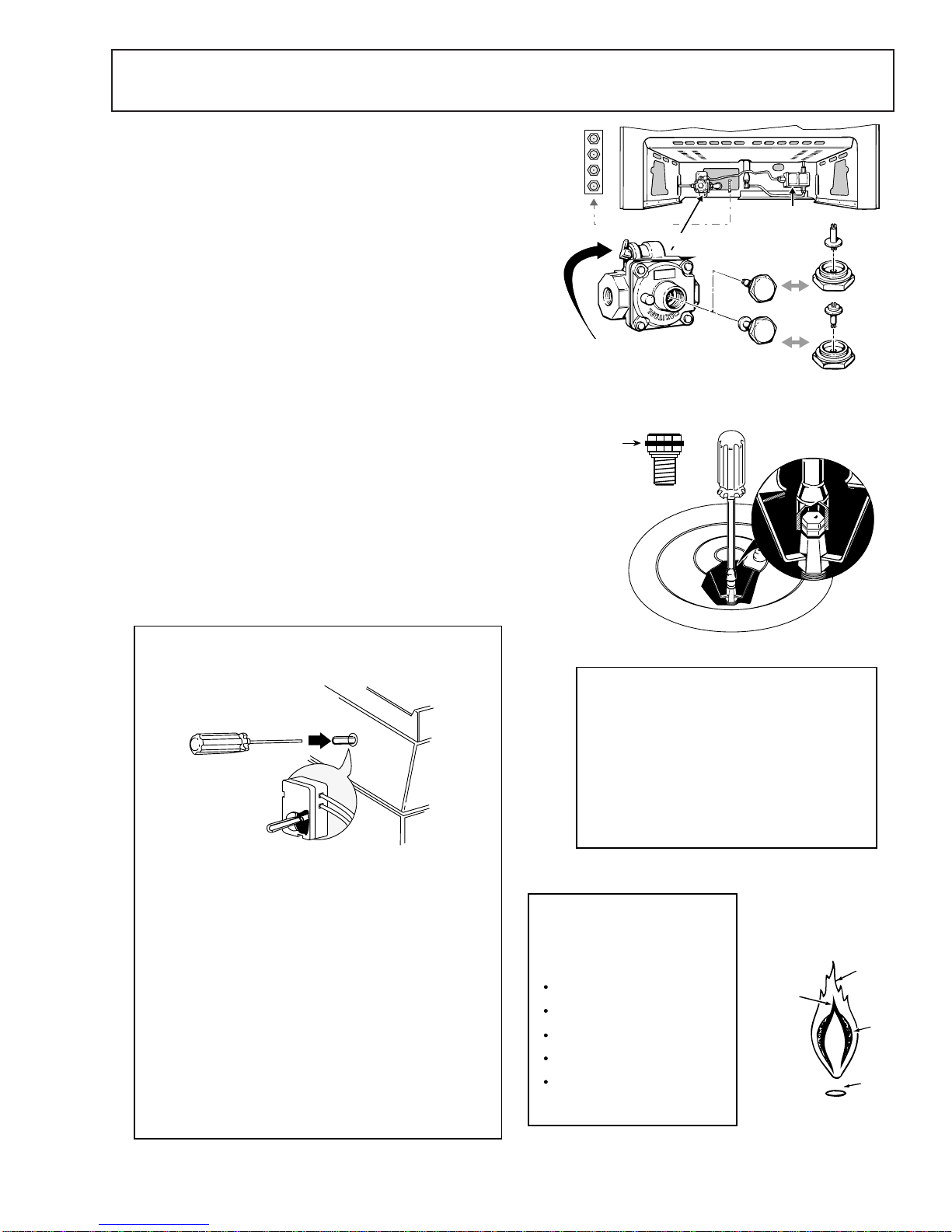
GE JGB910 and Comment utiliser

C
PUB # 31-9046 03/00
C
MODEL SERIES:
TECHNICAL SERVICE GUIDE
GE Consumer Service Training
XL44TM Self-Cleaning Gas
Convection Ranges
JGB910
JGB920

IMPORTANT SAFETY NOTICE
The information in this service guide is intended for use by
individuals possessing adequate backgrounds of electrical,
electronic, and mechanical experience. Any attempt to repair a
major appliance may result in personal injury and property
damage. The manufacturer or seller cannot be responsible for the
interpretation of this information, nor can it assume any liability in
connection with its use.
WARNING
If the information in this manual is not followed exactly, a fire or
explosion may result causing property damage, personal injury or
death. If you smell gas:
- Do not try to light any appliance.
- Do not touch any electrical switch; do not use any phone in
the building.
- Immediately call the gas supplier from a neighbor’s phone.
Follow the gas supplier’s instructions.
- If you cannot reach the gas supplier, call the fire department.
CAUTION
To avoid personal injury, disconnect power before servicing this
product. If electrical power is required for diagnosis or test
purposes, disconnect the power immediately after performing the
necessary checks.
RECONNECT ALL GROUNDING DEVICES
If grounding wires, screws, straps, clips, nuts, or washers used
to complete a path to ground are removed for service, they must
be returned to their original position and properly fastened.
GE Consumer Service Training
Technical Service Guide
Copyright © 2000
All rights reserved. This service guide may not be reproduced in whole or in part
in any form without written permission from the General Electric Company.
!

– 1 –
Table of Contents
Table of Contents
Description of Range .......................................................................................2
Installation of the Range ..................................................................................2
Cooktop Removal .............................................................................................4
Conversion to L.P. (Propane) Gas ..................................................................5
Upper Control Panel Access............................................................................7
Lower Control Panel Access............................................................................9
Warming Zone ....................................................................................................9
Convection Oven Fan ......................................................................................10
Warming Drawer ................................................................................................11
Special Features ...............................................................................................12
Fault Code Memory Display . ...........................................................................14
On-Board Diagnostic Tests .............................................................................16
Door Latch Mechanism ....................................................................................18
Troubleshooting................................................................................................19
Schematics and Strip Circuits .........................................................................21
Wiring Diagram ..................................................................................................25
Warranty Information.........................................................................................27


– 4 –
Cooktop Removal
1. Remove electrical power to the range. Turn off gas at
the main valve.
2. Lift off burner grates, caps, and burner heads.
3. Remove 8 screws holding burner bases to cooktop.
4. Lift bases and graphite seals off cooktop.
5. To release cooktop, disengage front clips (A) using a
flat blade screwdriver.
6. Gently raise the top high enough for the prop rods to
holditupright.
NOTE: When the cooktop is raised, the gas jets and
warming zone unit are accessible for repair.
7. Remove 4 wires (B) connected to the warming zone.
8. Disengage the prop rods from the range side panel.
Lift off the cooktop.
9. When reinstalling burner heads, make sure the nipple
in the burner head is positioned toward the electrode.
Rotate the burner head around the burner base until
it is level and securely seated.
Grate
Burner head
Burner cap
Electrode
Burner base GEA0012
4
GEA00134
Venturi
Assembly
Glass
Cooktop
B
urner
B
ase
Burner
Head Burner
Cap
Fiber Gask
et
Graphite Seal
GEA0012
3
BA
A

– 5 –
GasValve
(SafetyValve)
LP Orifice Spuds
Natural
LP
Pressure Regulator
SHUT OFF LEVER
Oven Only
Lever shown "CLOSED"
Pull lever to "OPEN"
Convert Regulator - Regulator is located in the lower, left
hand rear corner of the range as viewed from the front.
Depending on the model, remove the storage drawer,
broiler drawer or false panel to access the regulator. Some
models with a broiler drawer will have a metal cover over
the regulator that must be removed for conversion and
reinstalled when conversion is complete.
To Convert - Remove the large hex-nut which is located in
the center of the regulator. Remove the plastic pin from
the bottom side of the cap, turn the pin 180 degrees and
snap the pin back into the cap. There are raised letters on
the flat side of the plastic pin, "NAT" and "L.P.". In the "LP"
position the end of the pin marked "NAT" should be
snapped into the bottom of the hex-nut.
Remove surfaced burners and replace all 4 top burner
orifices spuds with the L.P. orifice spuds supplied with the
range (refer to the Technical Data Sheet supplied with the
product for proper L.P. spud location and orifice color
identification).
Using a 1/2" wrench, tighten the orifice hood(s) supplying
gas to the oven burner(s) clockwise until snug.
Open the air shutter on the oven burner(s) to the full open
position and adjust as needed.
Adjust the low flame (simmer) setting on the surface
burners.
2
3
4
5
1
The top burner valves have low flame/simmer
adjustment screws in the center of the control shafts. A
flashlight may be required to locate the screw. A small
thin blade screwdriver (approx. 3/32" blade width) is
needed to engage the screw.
TO ADJUST THE LOW FLAME SETTING - at least two
other burners must be lit. Light the burner being adjusted
and turn the knob to "LOW". Remove the knob and
insert the screwdriver into the shaft of the control valve.
Turn the adjustment screw to obtain the desired flame
size.
TEST FLAME STABILITY - by quickly turning the knob
from "HI" to "LOW". If the flame goes out, increase the
flame size and test again. Also, test flame stability by
quickly opening and closing the oven door. If the flame
is extinguished by the air current created by the door
movement, increase the flame size.
LOW FLAME (SIMMER) ADJUSTMENTS
The top burner orifices can be removed by
removing the burner cap and burner heads.
Using a 7 millimeter (mm) or a 9/32" nut-driver
carefully slide the driver down over the orifice
and rotate counterclockwise to remove.
IMPORTANT NOTE: The orifices have a spring
loaded retaining ring around the hex head to
hold the orifice in the nut driver during
installation and removal. A slight amount of
force is required to push the nut driver down
over the ring.
Retaining
Ring
YellowT
ip
& Soot
Outer
Cone
Flame Lif
ts
Off Burne
r
Inner Cone
PushedThrough
Outer Cone
IMPROPER FLAME
Yellow Tips, Soot and/or
Flame Lifting off Burner
TOP BURNER FLAME ADJUSTMENTS
The top burners do not have air shutters
adjustments and use non-adjustable
orifices. If the flame lifts off of the
burner, or if you experience "Yellow Tip"
flames and/or soot in the flames, be sure
to check the following:
Gas pressure: 4" W.C.P. (natural) and
10" W.C.P. (L.P.)
Inspect orifice to be sure it is drilled in
the center and free of debris or burrs.
Be sure the correct size orifice is in
the proper location
Make sure the range was properly
converted if on L.P.
If the cause of sooting can not be
found in the above checks, replace
the orifice with one having a smaller
diameter opening
Conversion to L.P. (Propane) Gas
5.
4.
3.
2.
1.

– 6 –
Air Adjustment
Shutter
Loosen
Air Adjustment
Shutter
Loosen
6Open the bake and broil air shutter adjustments as far as possible and adjust later if necessary.
Beneath the bake and broil burner orifice hoods are LP orifice needles. To convert to L.P. tighten the orifice hood
s
against the orifice needle until the hoods are snug (2-2½ turns). DO NOT OVER TIGHTEN. Check the burners fo
r
proper flame adjustment. The burner flame should have approximately 1" blue cones. With most LP gas, sma
ll
yellow tips at the end of outer cones are normal. flames should not lift off burner ports. If lifting is observed
,
gradually reduce the air shutter opening until flames are stabilized.
BAKE BURNER
ADJUSTMENTS BROIL BURNER
ADJUSTMENTS
6.

– 7 –
Upper Control Panel Access
Remove Control Panel
1. Grasp the light panel cover at the rear, where it is
hinged to the control panel. Lift upward at the rear,
just far enough to insert a small, thin bladed screw-
driver between the end cap and the fluorescent light
cover. Be sure to wrap the blade of the screwdriver
with tape to avoid scarring the plastic shield. Slide
the blade forward toward the front while lifting up the
cover.
2. Remove screws (A) and (B) that secure the endcaps
to the control console. Be careful when removing the
endcap not to break the locating tab at the bottom of
theendcap.
3. Loosen screw C2 turns. This screw is just long
enough that it will protrude into a slot in the side
frame, causing the panel to bind as you slide it down
and forward. Loosening the screw a couple of turns
will back it off enough that it will no longer protrude
into the side frame slot.
4. Grasp the face panel at the bottom front with one
hand, while gently pushing down on the top of the
control panel with your other hand. Pull control panel
downward to release it from the vent deflector while
at the same time pulling the panel forward from the
bottom.
Remove Capacitive Touchpad
1. Remove 2 screws at each end of the control panel.
2. Carefully separate the control panel from the
touchpad to avoid damaging the seal strips above
and below the touchpad.
NOTE: On the circuit board behind the control panel is a
circuit jumper that may fall off during disassembly. When
reconnecting the jumper, be sure to position it on the left
and center pins. Incorrect assembly of the circuit
jumper will result in ECP failure.
HINGED ON
BACK SIDE
FLIP PANEL UP TO ACCESS
FLOURESCENT LIGHT
LOOSEN
THIS SCREW TO
RAISE CONTROL PANEL
B
E SURETAB IS
I
N SLOTWHEN
R
EINSTALLING
REMOVE 2 SCREWS
TO REMOVE TOUCHPAD
A
BC
SIDE
FRAME
VENT DEFLECTOR
Pull control panel
down and forward to
release it from the
vent deflector
GEA0017
0
Circuit
Jumper

– 8 –
PUSH UP ON
VENT LIP
LOWER PANEL
INTO PLACE
SPARK MODULE
The spark module is located behind th
e
control panel, on the right side. You mus
t
remove the control panel to access th
e
spark module.
R
EINSTALLING CONTROL PANEL
W
hen reinstalling the control panel, push
u
p on the vent lip with your fingers. At the
s
ame time pull forward on the control
p
anel, making sure that the vent lip is
T
UCKED UNDER the control panel while
l
owering the panel into place. SPARK
MODULE
BALLAST
TABS
TUCK VENT LIP UNDER CONTROL
PANEL PRIOR TO LOWER PANEL
GEA00127
REINSTALLING CONTROL PANEL
When reinstalling the control panel, push up
on the vent lip with your fingers. At the same
time, pull forward on the control panel,
making sure that the vent lip is tucked under
the control panel while lowering the panel
into place.
SPARK MODULE
The spark module is located behind the control panel on
the right side. You must remove the control panel to
access the spark module.
Autres manuels pour JGB910 and
3
Ce manuel convient aux modèles suivants
3
Table des matières
Autres manuels GE Gamme

GE
GE JHP67GD Instructions d'installation

GE
GE JGBS20WEHWW Manuel

GE
GE JGBS04PPM Manuel

GE
GE JB391GK Manuel utilisateur

GE
GE AGBS45DEF1WS Manuel utilisateur

GE
GE JSP57 Manuel utilisateur

GE
GE Artistry ABS45DFBS Manuel utilisateur

GE
GE XL44 V series Comment utiliser

GE
GE JBP79 Manuel utilisateur

GE
GE JGB428SERSS Manuel

GE
GE Profile PHS925STSS Manuel

GE
GE 184-6C088-R1 Manuel utilisateur

GE
GE JCAS724 Mode d'emploi

GE
GE QuickClean JBS15M Manuel

GE
GE Profile PGS908 Manuel utilisateur

GE
GE JGBC20WEHWW Instructions d'utilisation

GE
GE JB640MRBS Manuel

GE
GE CS975SDSS Manuel

GE
GE Quick Set V Manuel utilisateur

GE
GE JBS60 Manuel utilisateur


