
Gator GTKPRO2 Manuel utilisateur

Quick Start Guide
GTKPRO2
GPS TRACKING
ADVANCED VEHICLE TELEMATICS
gatortracking.com.au

Table of contents..............................................2
Information guide.............................................3
Introduction...........................................3
Not included.....................................................4
Detailed product overview................................4
Knowing your device........................................5
Setting Up Your Device.....................................6
Wiring diagram.................................................8
Installation........................................................9
Led indications................................................10
Location and orientation considerations.........11
Server connection and new account setup....12
Login screen....................................................13
Main screen.....................................................14
Add object.......................................................15
Devices.........................................................16
Technical specifications..................................17
Technical assistance......................................20
TABLE OF CONTENTS:
2

3
INFORMATION GUIDE:
This quick start guidel is considered correct at the time of printing but is subject to change.The guide is
under constant review and revision,as is the server software constantly being improved and updated.
We recommend you download the latest version of the guide,as well as check for more information and
instructional videos from our website at Gatortracking.com.au
INTRODUCTION:
The GTKPRO2 vehicle tracking,telematics device is supplied with all the equipment that is necessary
for basic tracking operation.The package contains:
• GTKPRO2 device
• Wiring harness
• Internal 3.7V 170 mAh rechargeable Li-ion battery. (To be connected upon installation)
• M2M SIM card (Operating exclusively on the Telstra M2M CatM1 network.(Includes 30 day operation
grace period to subscribe.SIM needs to be inserted at time of installation)
IMPORTANT NOTE:
The following instructions are based upon this unit being connected to the Gator Server which requires
an active paid subscription to be entered into within 30 days of activation of the SIM card in this device.
If you wish to use this device on an alternate service,you will need to request that the unit be Reset in
open configuration mode.

4
NOT INCLUDED:
• 5 pin 30 or 40A Automotive relay required for ignition disable function and
2 additional other functions if required.Recommended part numbers:
Narva P/N 68028 12V 40A,Aerpro P/N RL40A 12V 40A or Bosch 0332209150.
For 24V applications a 24V relay must be used.
Recommended part numbers:
Narva 68052 or Bosch 0332209203
Also not included:
• CAN Data Interface.Gator Part number GCAN1 and GCAN2
• Bluetooth remote sensors.(Third party supplied)
DETAILED PRODUCT OVERVIEW:
The GTKPRO2 is a professional real-time tracking device with GNSS and LTE CAT-M1 connectivity and
backup battery. This device is pre-configured to Simultaneously use the US based GPS and the
Russian based GLONASS global satellite navigation systems.This device also includes a Bluetooth
transceiver for remote sensors (Sensors sold separately) and a 4G network LTE CAT-M1 transceiver for
data communications to the tracking server.This device is pre-configured with ignition sensing,door
sensing and SOS button inputs and has 3 digital control outputs that can operate an external relay for
various/ custom functions,one of which is reserved for remote ignition disable functionality. It is
perfectly suitable for fleet management,car rental companies,taxi companies,public transport,logistics
companies and personal vehicles.

5
KNOWING YOUR DEVICE:

6
SETTING UP YOUR DEVICE:
1.Gently remove bottom cover using plastic pry tool from both sides. Then remove the top cover.
2.Insert the supplied M2M Micro-SIM card.Make sure that Micro-SIM card cut-off corner is pointing
forward to the left looking from above.
Figure 1 Cover removal Figure 2 SIM card insert
NOTE: DO NOT INSERT THE INCLUDED SIM CARD IN ANY OTHER DEVICE OTHER THAN THIS
TRACKER.DOING SO WILL PERMANENTLY DISABLE THE SIM)

7
Right now is a good time to take a photo of the top of your unit with your smart phone or to notate
the IMEI number of your device.You will need this in order to register the device on the server.
SETTING UP YOUR DEVICE:
3.Connect the battery as shown to device.Position the battery in place where it does not obstruct
other components.(Especially the Transceiver modules (large square metal can looking components)
Do not insert a 3rd party SIM card in this device.
4.Re attach the cover.
Figure 3 Battery connection Figure 4 Attaching cover back

8
!"#
!"#$%&'()"*+
,$-./$0/
*#/123
4#/%#*/5$-./*+6-/76%./8/5)9*#":/
5$-./0"#*.9*-/*+6-/;6"6%<=
$%&'()"*&+,-.,-&/&012&3,-4
$5&'()"*&$#06(#&+,-.,-
%&70#(&389&:87(#
%&70#(&389&;"-"
%&'(;&%5<5=>&02
$?&'()"*&$#06(#&+,-.,-
$&@2.,-&?
$&@2.,-&5
$&@2.,-&%&/&@120-082&4
@2.,-&A&/+.-&!BC&D8;,)(4
0120-082&
#(-,#2&
:02E
5
%
FC$&/G4
!"#$%&"'(&)*+"',+-'$./$)$+/'01)'+,,',1/0)$+/2'
!"#$%&'$'()*&'%+$%', *'&-&./, *&0'1+&- '% + &'2&3',*', -'%+&',/-, %,"-'"-'
4"*,%, "-'"-&'+$*'-"'4 "1&.'1+&-'%+&'2&3', *'"(('".',-'%+&'
$##&*".3'4"*,%,"-5'6+-'%+&'()*&',*'.&7"8&0',%'*%"4*'%+&'8&+,#$9'
(."7'*%$.%,-/:*%"4&*',%'(."7'.)--,-/',('$9.&$03'.)--,-/5'
'
6,%+'%+&'()*&'.&7"8&0 ;'-"%&'1,#+'*, 0&',*'% +&'*") .#&'$*'%+&'"-&'
%+$%'*%,99'+$*'4"1&.'1,%+'%+&'()*&'.&7"8&05
<$2&'%+&'#)%'=&+,-0'%+&'>&%).-'*,0&'1,.&'?'1,%+'%+&'()*&'*%,99'
.&7" 8&0'@'$- 0'.&49 $#&'%+&'()*&'$(% &.'3").'1,.,-/'"('% + &'.&9 $3', *'
#"749 &%&5
H
%I
%%
%%
@2.,-&J&/+.-&!BC&98;,)(4
K,E(&
?B
>#/&##"/-;6*9+/#"/&#?./76<+*/8/!"#$%&//;+.%/&##"//#0.%=
@A@ /B #?.%*)":/-;6*9+
?
=
J
A
L
M
C<%6*6#%/
@#$"9.
MA
ML
ML"
?I
D23/E/06%/".7):
FG'GDH/9#%-*)%*/
0#;."/-#$"9.
>#/&.I69./0#-)*6I./;6"./: #$/;6-+/*#/0#;."/#%/
".?#*.7:J/
K.5/LG/".7):/#$*0$*/M.7#;
G2N123/E/06%/".7):/#"/
D/06%/".7):
O$*/M.+6%&/*+./
5$-./9#%.9*6#%
ML
ML"
MJ MA
?I
K,E(
L#/%#*/9#%%.9*
N0-O&-O(&P,E(&#(986(;Q&-O0E&E0;(&8P&-O(&P,E(&O8);(#&)88E(E&
.87(#
K,E(&
?B
FG'GDH/9#%-*)%*/
0#;."/-#$"9.
MJ
WIRING DIAGRAM:

9
!"#
!"#$%&'()"*+
,$-./$0/
*#/123
4#/%#*/5$-./*+6-/76%./8/5)9*#":/
5$-./0"#*.9*-/*+6-/;6"6%<=
$%&'()"*&+,-.,-&/&012&3,-4
$5&'()"*&$#06(#&+,-.,-
%&70#(&389&:87(#
%&70#(&389&;"-"
%&'(;&%5<5=>&02
$?&'()"*&$#06(#&+,-.,-
$&@2.,-&?
$&@2.,-&5
$&@2.,-&%&/&@120-082&4
@2.,-&A&/+.-&!BC&D8;,)(4
0120-082&
#(-,#2&
:02E
5
%
FC$&/G4
!"#$%&"'(&)*+"',+-'$./$)$+/'01)'+,,',1/0)$+/2'
!"#$%&'$'()*&'%+$%', *'&-&./, *&0'1+&- '% + &'2&3',*', -'%+&',/-, %,"-'"-'
4"*,%, "-'"-&'+$*'-"'4 "1&.'1+&-'%+&'2&3', *'"(('".',-'%+&'
$##&*".3'4"*,%,"-5'6+-'%+&'()*&',*'.&7"8&0',%'*%"4*'%+&'8&+,#$9'
(."7'*%$.%,-/:*%"4&*',%'(."7'.)--,-/',('$9.&$03'.)--,-/5'
'
6,%+'%+&'()*&'.&7"8&0 ;'-"%&'1,#+'*, 0&',*'% +&'*") .#&'$*'%+&'"-&'
%+$%'*%,99'+$*'4"1&.'1,%+'%+&'()*&'.&7"8&05
<$2&'%+&'#)%'=&+,-0'%+&'>&%).-'*,0&'1,.&'?'1,%+'%+&'()*&'*%,99'
.&7" 8&0'@'$- 0'.&49 $#&'%+&'()*&'$(% &.'3").'1,.,-/'"('% + &'.&9 $3', *'
#"749 &%&5
H
%I
%%
%%
@2.,-&J&/+.-&!BC&98;,)(4
K,E(&
?B
>#/&##"/-;6*9+/#"/&#?./76<+*/8/!"#$%&//;+.%/&##"//#0.%=
@A@ /B #?.%*)":/-;6*9+
?
=
J
A
L
M
C<%6*6#%/
@#$"9.
MA
ML
ML"
?I
D23/E/06%/".7):
FG'GDH/9#%-*)%*/
0#;."/-#$"9.
>#/&.I69./0#-)*6I./;6"./: #$/;6-+/*#/0#;."/#%/
".?#*.7:J/
K.5/LG/".7):/#$*0$*/M.7#;
G2N123/E/06%/".7):/#"/
D/06%/".7):
O$*/M.+6%&/*+./
5$-./9#%.9*6#%
ML
ML"
MJ
MA
?I
K,E(
L#/%#*/9#%%.9*
N0-O&-O(&P,E(&#(986(;Q&-O0E&E0;(&8P&-O(&P,E(&O8);(#&)88E(E&
.87(#
K,E(&
?B
FG'GDH/9#%-*)%*/
0#;."/-#$"9.
MJ
INSTALLATION :
When wiring up your device,please pay careful attention to the dual colours of some wires.
Connecting power source
Be sure to locate your constant power wire after the car computer goes to sleep mode this may happen
in 5 to 30 minutes period after turning the car off and removing the key.
After installation,measure the voltage at the module again to make sure it has not decreased.
It is recommended to connect to the main power cable in the fuse box.A 3A,125 V external fuse should
be used (At the source).
Connecting the ignition wire
Be sure to check if it is a real ignition wire ie.power does not disappear after starting the engine.
Check if this is not an ACC wire (when key is in the first position,most of the vehicle electronics are
available).
Connecting ground wire
Ground wire is connected to the vehicle frame or metal parts that are fixed to the frame.If the wire is
fixed with the bolt,the loop must be connected to the end of the wire.For better contact scrub paint
from the spot where loop is going to be connected.
After wiring is complete
This device comes pre-configured and does not require any post installation configuration/setup.
If operating correctly the unit will make immediate contact with the cellular network,The SIM card will
Authenticate that it is in the correct device and activate.The device will then make contact with the
tracking server and will be ready to add to our account when you go online.
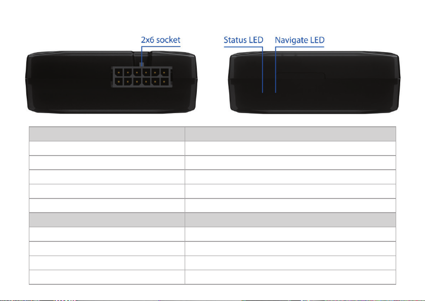
10
LED INDICATIONS :
NAVIGATION LED INDICATIONS
Permanently on
Blinking every second
Off GNSS is turned off
Blinking fast constantly
STATUS LED INDICATIONS
Blinking every second
Blinking every two seconds
Blinking fast for a short time
Off
BEHAVIOUR MEANING
GNSS signal is not received
Normal operation,GNSS is working
Device is not working or Device is in sleep mode
Device firmware is being flashed
BEHAVIOUR MEANING
Normal mode
Sleep mode
Modem activity
Device is not working or Device is in boot stage
Table des matières
Autres manuels Gator GPS

Gator
Gator GTRACK4G Manuel d'exploitation

Gator
Gator M508 Manuel utilisateur

Gator
Gator GTRACK3G Manuel utilisateur

Gator
Gator iDriveZ Navi 430 Manuel utilisateur

Gator
Gator M518 Manuel utilisateur

Gator
Gator GTRAKPRO Guide de l'utilisateur

Gator
Gator GTRACK 4G Manuel d'exploitation

Gator
Gator M508 Manuel utilisateur

Gator
Gator PT350 Manuel utilisateur

Gator
Gator M588T Manuel utilisateur


