GATEXPERT DKC500DCL Manuel utilisateur

Sliding Gate Opener
User Manual
DKC500DCL/DKC800DCL
Website: www.gatexpertstore.com
E-mail: sales@gatexpertstore.com

Instructions for DKC500DCL/DKC800DCL
www.gatexpertstore.com
WARNING
☆Instructions must be read before installation. Please follow these instructions carefully,
incorrect installation could affect gate operation.
☆When mounting and positioning this product please ensure the power cable is
unplugged.
☆The motor cover will need to be removed to mount the motor to the mounting plate or
directly to the concrete footing.
☆Any changes to the settings on this product can only be made by a licensed electrician.
☆This product can be powered by AC110V/220V power supply or backup battery power
and solar power.

Instructions for DKC500DCL/DKC800DCL
www.gatexpertstore.com
WARRANTY
1. To repair against this warranty card and invoice during the warranty period.
2. Warranty period: 1 year after the date of invoice.
3. Without unauthorized dismantling, any product broken or damage due to quality problem,
we’ll offer the repair service for free or replace for free.
4. The malfunction and damages caused by incorrect use or man fault is not covered by this
warranty.
CONTACT US
E-mail: sales@gatexpertstore.com
Please fill in the order information in the form below.
All personal information you provided will be only used for warranty service and kept
strictly confidential.
Refer to this list when contacting GATEXPERT for technical service or assistance with
your automatic gate opener.
Order Number
Product Model
Purchase Date
Country / Region
Email Address
Issue Details

Instructions for DKC500DCL/DKC800DCL
www.gatexpertstore.com
CONTENTS
Default Setting Instruction..............................................................................................................1
Safety Instruction.............................................................................................................................2
Parts List...........................................................................................................................................3
Technical Parameters......................................................................................................................5
Installation........................................................................................................................................5
Before You Start..........................................................................................................................5
Tools Required / Example Sliding Gate………............................................................................6
Step 1 - Gate Preparation............................................................................................................6
Step 2 - Checking Manual Release.............................................................................................7
Step 3 - Removing / Installing Motor Cover.................................................................................7
Step 4 – Motor Pad Footing.........................................................................................................8
Step 5 - Fitting Mounting Base and Motor....................................................................................8
Step 6 - Sprocket and Chain & Motor Alignment.......................................................................10
Step 7 - Limit Switch Stops........................................................................................................11
Step 8 - Powering on........................……..................................................................................13
Step 9 - Testing Travel and Limit Stops.....................................................................................14
Programming and Wiring..............................................................................................................15
DIP Switch Adjustment..............................................................................................................16
Potentiometer Adjustment.........................................................................................................17
Terminal Instructions.................................................................................................................18
Wiring to the Terminal...............................................................................................................20
Connecting Infrared Photocells.................................................................................................21
Remote Control Operation........................................................................................................22
Connecting Storage Battery......................................................................................................22
Connecting Solar Panel.............................................................................................................22
Wiring to the Transformer..........................................................................................................23
Maintenance...................................................................................................................................23
Troubleshooting.............................................................................................................................24
Drawing and Measurements..........................................................................................................25

Instructions for DKC500DCL/DKC800DCL
www.gatexpertstore.com
1
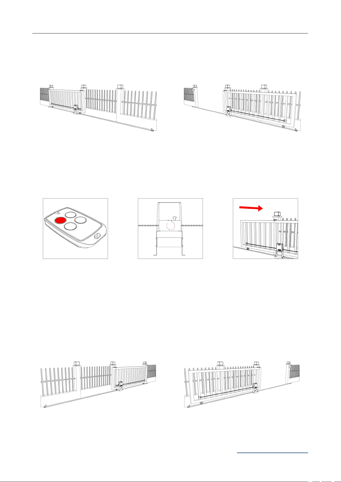
Then the gate will move in
the set direction.
Default Setting Instruction
The gate opener will open the gate to the right-hand side as its default setting. By default, the
opener mounts on the right-hand side. (Figure 1)
Gate in closed position Gate in open position
Figure 1
Before installation: Test the gate opener by plugging it into a power source and pressing the
remote. Press the opening button, the output sprocket rotates, then press the stop button, the
output sprocket stops rotating. Finally, press the closing button, the output sprocket rotates to the
opposite direction. This will give you an understanding of the way how the opener moves the gate.
Figure 2
Note: Ensure that the gate opener is unplugged before proceeding with installation. Please keep
fingers away from the motor output sprocket whilst it is turning.
If your gate needs to open from the other direction (to the left, refer to figure 3), your opener needs
to be mounted on the left-hand side as shown, the relative wires need to be swapped over, please
check under “Terminal Instructions” for swapping. (Factory default setting is for right-hand opening:
opener mounted on the right-hand side).
Figure 3
Any works done to the gate opener must be completed whilst the power is off, and the opener is
unplugged.
Press the first/top button
on the remote.
Rotating output sprocket will
drive the gate frame.

Instructions for DKC500DCL/DKC800DCL
www.gatexpertstore.com
2
Safety Instruction
Warning: Incorrect or improper use of this product can cause damage to persons, animals or
properties.
·Please ensure that the input voltage used matches with the supply voltage of gate opener.
·All modifications to wiring or electrics, and any adjustment or maintenance to input voltage
must be done by a qualified electrician.
·All potential hazards and exposed pinch points of the gate must be eliminated or guarded prior
to installation of this gate opener.
·Never mount any device that operates the gate opener where the user can reach over (under,
around or through) the gate to operate the controls. These must be placed away from any
moving range of the moving gate.
·Ensure power plug is disconnected from the power socket during installation or maintenance.
·Keep remote control and other control devices out of children’s reach, in order to avoid
unintentional activation.
·To ensure safety, before installing the motor, mount a Gate End Catch and a Gate Stop at each
end of the rail to prevent the gate travelling off the track.
·If required, install infrared photocell to detect obstructions and prevent injury to person or
damage to property.
·Instruct all users about the control systems provided and the manual opening operation in case
of emergency.
·Ensure that the power cable is connected to a RCD protected weatherproof power outlet
installed by a qualified electrician.
·Do not install this product in an explosive atmosphere or where there is any danger of flooding.
·This product was exclusively designed and manufactured for the use specified in the present
documentation. Any other use not specified in this documentation could damage the product
and be dangerous.
·Only use original parts for any maintenance or repair operation. Our company declines all
responsibility with respect to the automation safety and correct operation when other supplier’s
components are used.
·Do not modify the automation components, unless explicitly authorized by our company.
·The user must avoid any attempt to carry out any works or repairs on this product, and should
always request the assistance of qualified personnel.
·This product is suitable for use on one sliding gate only.
·Anything which is not expressly provided for in these instructions is not allowed and will void
warranty.
·Dispose of all packing materials (plastic, cardboard, polystyrene etc.) according to current
guidelines. Keep plastic bags and polystyrene out of children’s reach.
·Save these instructions for future use.

Instructions for DKC500DCL/DKC800DCL
www.gatexpertstore.com
3
Parts List
Parts List (standard configuration)
No.
Picture
Name
Quantity
1
Motor
1
2
Manual Release Keys
2
3
Remote Controls
2
4
Mounting Accessories Box
1
4-1
Sprocket Cover
1
4-2
Chain(Including 2 Chain Links)
6m
4-3
Tie Rod
2
4-4
Square Screw
4
4-5
Round Screw
4
4-6
Door Connecting Plate
2
4-7
Horizontal Mounting Plate
1
4-8
Vertical Mounting Plate
2

Instructions for DKC500DCL/DKC800DCL
www.gatexpertstore.com
4
No.
Picture
Name
Quantity
4-9
Anchor Bolts M8
4
4-10
Magnetic Limit Switch Stop
2
Magnets
2
Hexagon Head Bolt M6X65
4
Nut M8
4
Flat Washer φ8
2
Spring Washers φ8
2
4-11
Inner Hexagon Head Bolt M6X20
4
4-12
Hexagon Head Bolt M8X40
4
4-13
Nut M6
16
Nut M8
16
4-14
Flat Washer φ6
16
Flat Washer φ8
16
4-15
Spring Washers φ6
16
Spring Washers φ8
12
Note: Extra flat washers and spring washers are spare parts.
Parts List (optional)
No.
Picture
Name
Quantity
1
Infrared Photocell
1
2
Wireless Keypad
1
3
Alarm Lamp
1

Instructions for DKC500DCL/DKC800DCL
www.gatexpertstore.com
5
Additional remote controls: Spare/Additional remotes for the automatic gate kit, these will need to
be paired to the motor.
Infrared photocell: Detects pedestrians, vehicles and objects that cross an infrared beam and
prevents the gate from closing.
Wireless keypad: Allows secure access through the gate used with a user set code.
Wired control: Allow users to control the opening and closing of the door through an external
push-button.
Alarm lamp: Alerts people near the gate and users that the gate is in operation.
Technical Parameters
Model
DKC500DCL
DKC800DCL
Power Supply
110VAC/60Hz; 220VAC/50Hz
Motor Power
150W
170W
Gate Moving Speed
13m/min
18m/min
Maximum Loading Weight
500KG
800KG
Remote Control Distance
≥30m
Remote Control Mode
Single button mode / Three button mode
Limit Switch
Magnetic limit switch
Working Noise
≤58dB
Working Duty
S2, 20min
Recording of up Remote Controls
40
Remote Frequency
433.92 MHz
Working Temperature
-20°C - +70°C
Package Weight
16.42KG
16.5KG
Installation
Before You Start
·DKC500DCL/DKC800DCL Sliding Gate Automation Kit is suitable for powering the opening
and closing motion of gates up to 600kg,800kg in weight, up to a length of 8m. (Standard kit
contains a 6m chain, if the gate length is over 5.5m, please consider to extend the length of the
chain.)
·Gate motion is achieved by the rotating output sprocket of the gate opener driving the chain
fitted to the moving gate.
·The gate opener requires you to press the remote control once to open, and once again to
close. This is a safety feature to ensure safe operation.
·The gate opener itself must be fitted within private property, never externally to a property’s
boundary.
Any works done to the gate opener must be completed whilst the power is off and the opener is
unplugged. Any modifications/alterations/works to AC power components must only be completed by
a licensed electrician.

Instructions for DKC500DCL/DKC800DCL
www.gatexpertstore.com
6
Tools Required
·Tape measure
·Level
·12mm concrete drill and hammer (when uses expansion screws)
·Phillips head screwdriver
·Straight screwdriver
Example Sliding Gate
Gate Track and Track Wheels Gate End Catch Gate Guide Rollers Gate Stop
Figure 4
Please ensure that the gate opener power cable is not plugged in at any stage before Step 8.
Step 1 - Gate Preparation
·Ensure that the sliding gate is correctly installed.
·The gate is horizontal and level and the gate can glide back and forth smoothly when moved by
hand before installing the gate opener.
·Wheels and guide rollers should rotate easily and be free from dirt or grime.
·Track should be flat, level and firmly affixed.
·Any misalignment in the gate will affect performance of the automatic gate opener.
The gate should slide smoothly by hand before attempting to install the gate opener.
Figure 5
Ce manuel convient aux modèles suivants
1
Table des matières
Autres manuels GATEXPERT ouvre-porte

GATEXPERT
GATEXPERT GT800ACL Manuel utilisateur

GATEXPERT
GATEXPERT GT1000DCL Manuel utilisateur

GATEXPERT
GATEXPERT DKC500ACL Manuel utilisateur

GATEXPERT
GATEXPERT GA500DC Manuel utilisateur

GATEXPERT
GATEXPERT INDUS-E Series Manuel utilisateur

GATEXPERT
GATEXPERT GA1000AC Manuel utilisateur

GATEXPERT
GATEXPERT SL500DC Manuel utilisateur

GATEXPERT
GATEXPERT PY300DC Manuel utilisateur

GATEXPERT
GATEXPERT GT1000DC Manuel utilisateur

GATEXPERT
GATEXPERT GA600AC Manuel utilisateur