
Gates Plus MOTSDC Manuel utilisateur

Installation Manual
N21430
MOTSDC Swing Motor
Gatesplus - 1300 121 666 1of 18

Contents
Warranty .......................................................................................................................................... 3
IMPORTANT SAFETY WARNINGS............................................................................................ 4
FEATURES ...................................................................................................................................... 5
Check Gate and Hinge..................................................................................................................... 6
Gate Stops......................................................................................................................................... 6
Master / Slave Motors...................................................................................................................... 6
Mounting the operators to the gate posts ...................................................................................... 7
Arm Assembling............................................................................................................................... 7
Manual Release ................................................................................................................................ 8
Install Arm........................................................................................................................................ 8
Cams Setting (Left Hand Motor Installation) ............................................................................... 9
Cams Setting (Right Hand Motor Installation) .......................................................................... 10
Slave motor (Left Hand Motor Installation) ............................................................................... 11
Slave motor (Right Hand Motor Installation)............................................................................. 11
Confirm CAMS Setting ................................................................................................................. 12
Engage the Opener......................................................................................................................... 12
Battery Connection ........................................................................................................................ 12
Program Remote control and receiver......................................................................................... 12
Confirm the Close and Open LED ............................................................................................... 13
Force Adjustment (sensitivity)...................................................................................................... 13
Auto Close....................................................................................................................................... 14
Leaf Delay ....................................................................................................................................... 14
Motor 1 and Motor 2 setup ........................................................................................................... 14
Electric Lock................................................................................................................................... 14
Wiring Diagram ............................................................................................................................. 15
Reduced Side Room and Outwards Opening.............................................................................. 16
Electrical and Mechanical Specifications .................................................................................... 17
Trouble Shooting ............................................................................................................................ 17
Standard Kit Contents................................................................................................................... 18
Motor Dimension ........................................................................................................................... 18
Gatesplus - 1300 121 666 2of 18

Warranty
The warranty is one year Back to Base Warranty. The warranty commences from the
date of purchase. Invoice must be retained for the warranty to be honored. Three
months warranty on the Remote Control.
The warranty cover defects of materials to the unit under normal and correct use.
The unit must be correctly installed. If the gate is not opening freely in a manual
mode, damage occurs and voids the warranty.
When problems arise within the warranty period, the customer must contact the
supplier to rectify the problems.
It is customers’ responsibility to engage in periodic maintenances and checks the
opener ever three months for insects, loose wiring, check battery, gate movement in
manual mode, greasing hinges, solar panel surface keep clean, loose bolts etc.
Failure to maintain the opener result the warranty null and void.
Warranty does not cover insects, water, battery, fuses, storm damage, improper use
or undue force.
Periodic maintenance is highly advised.
Gatesplus - 1300 121 666 3of 18

IMPORTANT SAFETY WARNINGS -
Please read these important safety warnings
before installing or using this product
•Never let children operate or play with the controls.
•Keep the remote control away from the children.
•Do not operate the swing gate unless the gate is in full view and free from
objects such as cars, children or people.
•Always keep the moving gate insight and away from any objects until it’s
completely opened/closed.
•No one should cross a moving gate.
•Do not disengage the swing gate motors to manual operation with anyone or
any other objects, including motor vehicles, within the doorway.
•The swing gate must be well balanced. Sticking or binding gates can falsely
trigger the obstruction sensing of the unit.
•All maintenance should be carried out by qualified personnel.
•Regularly test the swing gate motor to ensure that the obstruction sensor unit
is operating properly.
•The swing gate motor has an electronic obstruction system that provides safe
and reliable operation. It’s however a legal requirement in some countries to
also install a photo-electric sensor across the door way, please check this
requirement with your local distributor. However, it’s recommended to install
this photo-electric sensor for all units.
Gatesplus - 1300 121 666 4of 18

FEATURES
Your automatic swing g ate motor has
many features which you will appreciate.
The components and materials used in its
control board are the latest technology and
highest quality.
The motor is use to drive the swing gates
with a moving speed of 90 degree in 15
seconds. This gate opener is powered by
12 Volt DC, or solar power. It is featured
with powerful starting speed.
OPERATION
To operate the swing gate simply presses
the remote control handset or the wall
mounted switch for one seconds and the
door will automatically open/close.
The gate can be stopped during opening or
closing cycle by pressing the remote
control handset or wall switch. The next
actuation will move the gate in the
opposite direction.
SAFETY OBSTRUCTION REVERSE
While the gate is performing closing cycle
and it should hit an obstacle or be
restricted in some manner, it will
automatically reverse.
The amount of force the gate should
encounter before reversing is adjustable.
The gate will automatically stop if
restricted while opening. The safety
Obstruction forces should be checked at
least once a month.
SENSITIVITY = FORCE SETING
Force Settings Must Be Adjusted
Before Running The Gate Opener
SECURITY CODE STORE
The swing gate motor uses state of the art
Microchip technology in storing your swing
code transmitter security code.
Up to 20 different transmitters can be stored in
the non-volatile memory device.
To store any code simply press the LEARN
button on the Receiver and press the
transmitter button once. The codes can be
deleted any time.
Security is enhanced because the fixed and
encrypted sections combined increase the
number of combinations to 7.38 x 10 . There
is no Dip switch on the motor which can be
visually seen and copied.
9
AUTO CLOSE MODE
The swing gate motor can be set to
automatically close at a selected period (e.g.
Thirty seconds) after the gate has opened.
A photo-electric beam must be installed if
this mode is selected. The circuit board also
has input for push buttons, key pads and
intercom.
PHOTO-ELECTRIC BEAM
The swing gate motor has input for a Photo-
Electric Beam to be connected for extra safety
protection.
POWER SUPPLY
The swing gate motors are powered by
15VDC plug pack or solar panel.
POWER FAILURE
Gates can be moved manually by inserting the
Allen key into motor
Gatesplus - 1300 121 666 5of 18

1: Check Gate and Hinge
Before install check the gate and hinge in good working condition, and the gate must be free
swinging without binding.
2: Gate Stops
It is recommended that any of the following are used:
* A tag on one gate
* Overlapping gate leaves
* Gate-stops at the limit of each leaf’s travel
3: Master / Slave Motors.
* The drive unit with the circuit board is the master Motor
* The drive unit without the circuit board is the Slave Motor
Gatesplus - 1300 121 666 6of 18
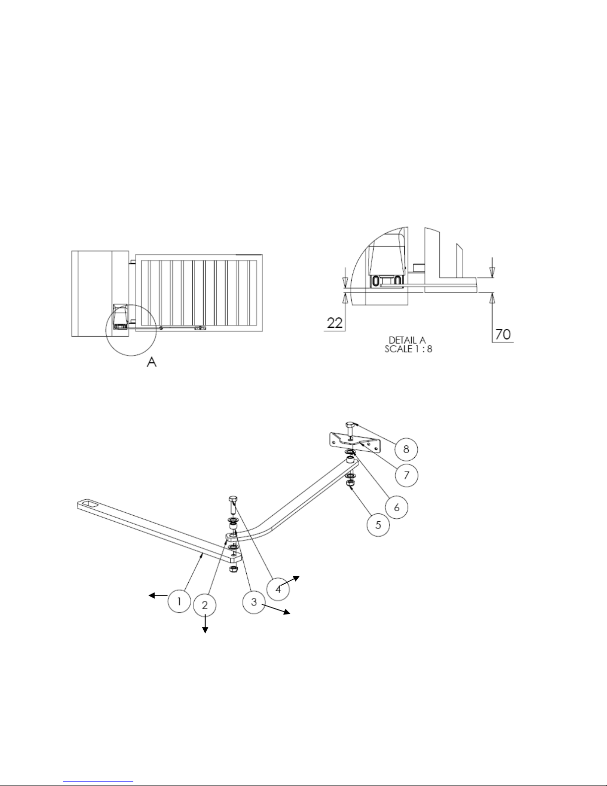
4: Mounting the operators to the gate posts
Important: do not modify this equipment, and do not power up, until all the
Setting is finish.
Install master motor first. (The one with the circuit board is the master motor.)
Mount the opener 50 mm from the inside edge of the gate
Post. Use fasteners of at least 10 mm diameter x 75 mm
Length. Use the template provide on top of the
Box. Drill 4 holes and mount it on.
mm
mm
5: Arm Assembling
2 x Lock Nuts
Long Bolt
2 x Nylon bushes
Second Arm
First Arm
4 x Washers
Bracket
Short Bolt
Gatesplus - 1300 121 666 7of 18

6: Manual Release
A: Disengage opener
You can disengage the gate from the opener. Using the provided Allen key, turning the Brass knob
On the underside of the opener clockwise as viewed from above.
B: Engage opener
Put the opener back into gear. Using the Allen key turn back the Brass knob Anti-clockwise. And
swing the gate until you feel the opener lock into gear.
To avoid possible damage to property or personal injury, please disengage the opener before making
limit switch adjustments. And do not connect any power. (See Section 6A)
7: Install Arm. Refer to the drawing below.
Dis-engage the opener, Move the gate into close position manually. You m ay turn the shaft by hand
when in manual, making it easier to mount the arms. Refer to the Drawing below. Do not mount the
arm to the gate dead straight.
Gatesplus - 1300 121 666 8of 18

8: Cams Setting (Left Hand Motor Installation)
Master Motor (Inside the property –looking out)
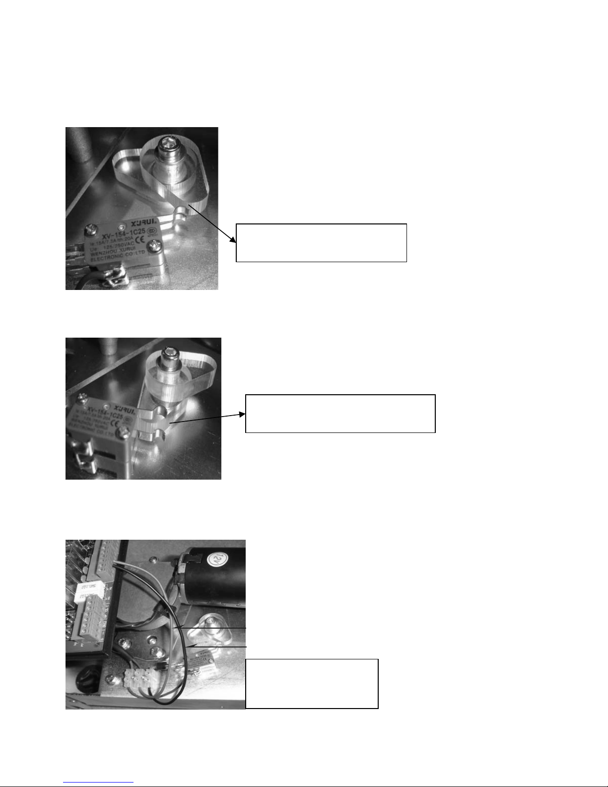
8A: Adjust Gate open limit (Top Cam) Left Hand Motor
When in Manual Mode, open the gate by hand to the position you
want it to stop in, as you do this, you will see the cams move in the
direction they are moving, you turn the cam around until it clicks
on the limit switch.
Top Cam (Open Limit)
Should be look like this photo
8B: Adjust Gate Close Limit (Bottom Cam) Left Hand Motor.
Close the gate in the close position. Rotate the bottom cam until it
actuates the switch. These can be done by moving a small
increment at a time.
Bottom Cam (Close Limit)
Should be look like this photo
8C: Wiring Installation (Left Hand Motor Installation).
Follow the wiring as shown below.
9: Cams Setting
Master Motor
Connect the red and
b
lack Wire to Motor 2.
Red wire
Black wire
Gatesplus - 1300 121 666 9of 18
9: Cams Setting (Right Hand Motor Installation)
Master Motor (Inside the property –looking out)
9A: Adjust Gate Close limit (Top Cam) Right Hand Motor
When in Manual Mode, Close the gate by hand to the position you
want it to stop in, as you do this, you will see the cams move in the
direction they are moving, you turn the cam around until it clicks
on the limit switch.
Top Cam (Close Limit)
Should be look like this photo
9B: Adjust Gate Open Limit. (Bottom Cam) Right Hand Motor
Open the gate in the Open position. Rotate the bottom cam until it
actuates the switch. These can be done by moving a small
increment at a time.
Bottom Cam (Open Limit)
Should be look like this photo
9C: Wiring Installation (Right Hand Motor Installation).
Follow the wiring as shown below.
Master Motor
Connect the red and
b
lack Wire to Motor 2.
Black wire
Red wire
Gatesplus - 1300 121 666 10 of 18
Table des matières
Manuels ouvre-porte de garage populaires d'autres marques


Craftsman
Craftsman 139.53924 Manuel utilisateur

Chamberlain
Chamberlain MyQ 940ESTD Manuel utilisateur

Automatic Technology
Automatic Technology GDO-9V1 SecuraLift Manuel utilisateur

Westfalia
Westfalia 19 36 07 Manuel utilisateur

Chamberlain
Chamberlain HD520EVP Manuel utilisateur

Cardin
Cardin BL Series Manuel utilisateur