Galil DMC-41x3 Manuel utilisateur

DMC-41x3 Installation Manual-ETL
DMC-41x3 Integrated
Amplifier Installation
Manual
Manual Rev. 1.0a3
By alil Motion Control, Inc.
Galil Motion Control, Inc.
270 Technology Way
Rocklin, California 95765
Phone (916) 626-0101
Fax (916) 626-0102
E-mail Address [email protected]
URL www.galilmc.com
Rev 02/29/12

Using This Manual
This manual provides information for the wiring, installation, powering-up, and basic communication
to the DMC-41x3 motion controller with the alil internal amplifiers, AMP-435x0 and AMP-432x0.
The following list of part numbers are examples of configurations of the DMC-41x3 motion controller
that are covered in this manual.
DMC-41x3
DMC-41x3-D3220
DMC-41x3-D3240
DMC-41x3-D3520
DMC-41x3-D3540
DMC-41x3-D3240-D3220
DMC-41x3-D3240-D3240
DMC-41x3-D3540-D3520
DMC-41x3-D3540-D3540
DMC-41x3-D3240-D3520
DMC-41x3-D3240-D3540
DMC-41x3-D3540-D3220
DMC-41x3-D3540-D3240
This manual covers the basic installation of the controller and amplifier modules. For full operational
information including specific I/O installation, detailed programming examples and additional internal
driver information, see the DMC-41x3 User Manual.
WARNIN : Machinery in motion can be dangerous! It is the responsibility of the user to
design effective error handling and safety protection as part of the machinery. alil shall
not be liable or responsible for any incidental or consequential damages.
If the DMC-41x3 motion controller and included amplifiers or stepper drivers are not used
in a manner specified by alil Motion Control, the protection provided by the controller,
amplifiers and drivers may be impaired.
Caution:
The DMC-41x3 controller with internal servo amplifiers
contain hot surfaces.

Chapter 1 Overview
Introduction
DMC- 1x3 Motion Controller
The DMC-41x3 Series are alil’s Econo motion controller that is a scaled-down version of the DMC-
40x0 Acclerra series controller. The controller series offers many enhanced features compared to prior
generation Econo series controllers including high speed communications, non-volatile program
memory, faster encoder speeds, and improved cabling for EMI reduction.
Each DMC-41x3 provides two communication channels: a high speed 100BaseT Ethernet connection
and a USB programming port. There is an auxiliary RS-232 port that can be used to communicate to
external devices such as HMI's. The controllers allow for high-speed servo control up to 15 million
encoder counts/sec and step motor control up to 3 million steps per second. Sample rates as low as 62
µsec per axis are available.
A Flash EEPROM provides non-volatile memory for storing application programs, parameters, arrays
and firmware. New firmware revisions are easily upgraded in the field.
The DMC-41x3 is available with up to eight axes in a single stand alone unit. The DMC-4113, 4123,
4133, 4143 are one thru four axes controllers and the DMC-4153, 4163, 4173, 4183 are five thru eight
axes controllers. All eight axes have the ability to use alil’s integrated amplifiers or drivers and
connections for integrating external devices.
Commands are sent in ASCII. Additional software is available for automatic-tuning, trajectory
viewing on a PC screen, and program development using many environments such as Visual Basic, C,
C++ etc. Drivers for Windows XP, Vista and 7 (32 & 64 bit) as well as Linux are available.
AMP- 3220/ 32 0 Servo Amplifier (-D3220/-D32 0)
The AMP-43240 and AMP-43220 amplifiers reside inside the DMC-41x3 enclosure. The AMP-43240
contains four transconductance, PWM amplifiers for driving brushless or brush-type servo motors (the
AMP-43240 contains 2 amplifiers). Each amplifier drives motors operating at up to 10 Amps
continuous, 20 Amps peak, 20–60 VDC. The gain settings of the amplifier are user-programmable at
0.5 Amp/Volt, 1.0 Amp/Volt and 2.0 Amp/Volt. The switching frequency is 24 kHz. The drive
operates in a Chopper Mode. The amplifier offers protection for over-voltage, under-voltage, over-
current, short-circuit and over-temperature. Two AMP-43240s or AMP-43220's can be used in 5- thru
8-axis controllers.

AMP- 3520/ 35 0 Servo Amplifier (-D3520/-D35 0)
The AMP-43540 and AMP-43520 amplifies reside inside the DMC-41x3 enclosure. The AMP-43540
contains four sinusoidally commutated, PWM amplifiers for driving brushless servo motors (the AMP-
43520 contains 2 amplifiers). Each amplifier drives motors operating at up to 8 Amps continuous, 15
Amps peak, 20–60 VDC. The gain settings of the amplifier are user-programmable at 0.4 Amp/Volt,
0.8 Amp/Volt and 1.6 Amp/Volt. The switching frequency is 33 kHz. The amplifier offers protection
for over-voltage, under-voltage, over-current, short-circuit and over-temperature. Two AMP-43540s or
AMP-43520's can be used for 5- thru 8-axis controllers.

Chapter 2 Installation
Pre-Installation
Operating Environment
The location for use of the DMC-41x3, AMP-432x0 and AMP-435x0 must meet the following
requirements.
Description Units Specification
Ambient Temperature C 0 to +40
Altitude feet 10,000
Humidity RH 20-95% (non-condensing)
Mounting Location
The DMC-41x3 motion controller must be mounted on a flat surface using the 4 mounting holes found
on the metal base-plate. The grating found on the side of the metal must not be obstructed in order
provide proper air flow for adequate heat dissipation. The dimensions for a 1-4 axis controller are
smaller than that of a 4-8 axis controller, these dimensions and the mounting hole locations are found
in Appendices A3 and A4.
Additional Mounting Consideration when using the AMP- 3xx0
When operating a DMC-41x3- D3xx0-D3xx0 or a DMC-41x3-D3xx0, special mounting
considerations must be made if the total continuous current output for the controller is greater than 15A
for a 1-4 axis controller and greater than 30A for a 5-8 axis controller. In this case, the controller base
must be mounted to an addition heat sink.
When the application requires that the DMC-41x3-D3xx0-D3xx0 be mounted to a heat sink, the heat
sink must be sized such that the base of the DMC-41x3 be kept at a temperature of 65O C or below.
This works out to a thermal resistance of 0.2O C/W at full continuous power. Full continuous power is
defined as a 100% duty cycle with all 8 axis running 10Amps continuous current (80 Amps total), with
a 60VDC bus.

Elements Needed for Installation
1. Isolated DC power supply
a. Ratings found in Appendix A1
2. Power Supply Cable
a. Cable from DC power supply to power input for AMP-43xx0.
b. DMC-4183 controller requires 2 cables.
3. PC or laptop with Ethernet and/or USB ports
4. alilTools, or alilTools-Lite software package
5. Ethernet Cable
a. Recommended shielded Cat 5 STP cable. Straight-through or Cross-over.
6. Male Type A – Male Type B USB cable
7. Molex pin Crimp Tool
8. Additional cables may be required for connection to motors, external amplifiers, digital or
analog I/O, and other devices. See the full DMC-41x3 User Manual for further information.
9. Disconnect switch or circuit breaker for AC power to DC Power Supply
Unpacking the Controller
Caution: The DMC-41x3 motion controller and included internal amplifier include electrostatic
sensitive components. Observe standard precautions for handling ESD sensitive devices
when handling the controller.
1. Verify that the following components have been shipped along the motion controller.
•Connectors and mating pins for motor power and amplifier power.
oQty 4 – 4 pin molex connectors for EACH internal amplifier
oQty 1 – 6 pin molex connector for EAH internal amplifier
•alil Software Installation CD
Note: Connectors and/or software installation CD may not be shipped to existing OEM
customers.
2. Check that no visible damage has occurred to the controller, or internal amplifiers. If any
damage has occurred to the controller, or the components shipped with the controller, contact
alil Motion Control immediately. Contact information can be found in the beginning of this
manual.
3. Verify the controller that has been shipped to you is in fact the controller that you have
ordered from alil or your authorized alil distributor. To do this, check the labeling on the
controller and compare it to the part number that was ordered.

Figure 1: Label for DMC-41x3
Figure 2: Label for DMC-41x3-D3220
Figure 3: Label for DMC-41x3-D3240
Figure 4: Label for DMC-41x3-D3520
Figure 5: Label for DMC-41x3-D3540

Figure 6: Label for DMC-41x3-D3240-D3220
Figure 7: Label for DMC-41x3-D3240-D3240
Figure 8: Label for DMC-41x3-D3540-D3520
Figure 9: Label for DMC-41x3-D3540-D3540
Figure 10: Label for DMC-41x3-D3240-D3520

Figure 11: Label for DMC-41x3-D3240-D3540
Figure 12: Label for DMC-41x3-D3540-D3220
Figure 13: Label for DMC-41x3-D3540-D3240
Figure 14: ETL Mark
Installation
Mounting the Controller
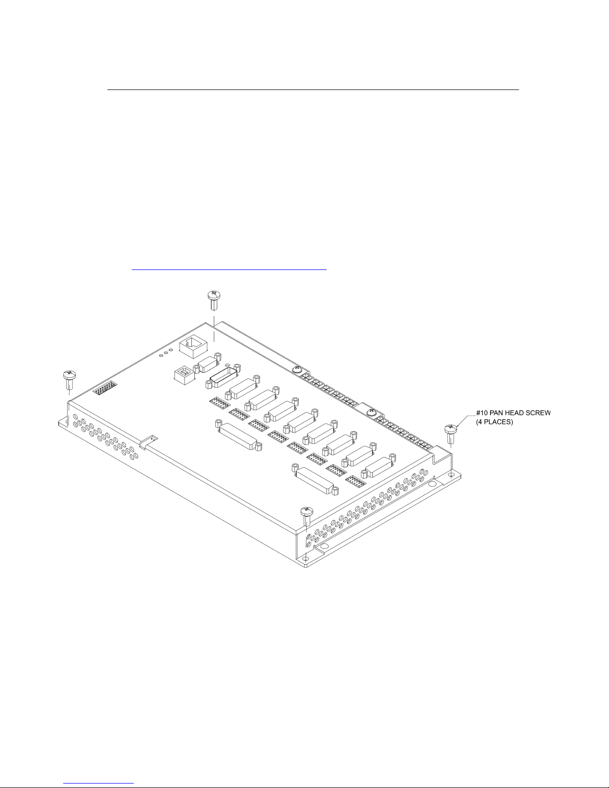
The DMC-41x3 motion controller must be mounted to a flat surface with 4 – #10 pan head screws
through each mounting hole found on the controller base as shown in Figure 15. If the controller is
mounted on a wall, the controller should be mounted so that the bottom of the controller is horizontal
to the floor (as shown in Figure 15). The enclosure must meet or exceed any fire ratings that are
required of the system as a whole.
If the AMP-43xx0 internal amplifiers are being used, it should be determined at this time whether or
not an additional heat sink will be required. This is determined based upon the continuous current
requirements of the system as defined in the “Additional Mounting Consideration when using the
AMP-43xx0” section above. The Motor Sizer tool found on our website can be used to determine this
value http://www.galilmc.com/learning/motorsizer.php.
Figure 15: Mounting the DMC-41x3
Powering the Controller
The DMC-41x3 is powered via the DC supply connections. All connectors share a common ground.
The DMC-41x3 is grounded through the metal enclosure and should be installed on an unpainted metal
surface. The Earth lugs should be used for additional electrical contact.
Table des matières
Autres manuels Galil Amplificateur


