G-Force AG 5 DC2 Manuel

© 2012 G Force Automac Gates All Rights Reserved
Model AG 5 DC2
Single Swing Gate Motor Kit
Solar Powered and 12V Low Voltage
June 2019
Installation and Set Up Instructions
Unit 27 / 49 Corporate Boulevard Bayswater Vic 3153 Phone 1800 111 930
Email info@gforceautogates.com.au Web www.gforceautogates.com.au

© 2012 G Force Automac Gates All Rights Reserved
Important Safety Warnings
Please read these important safety warnings before attempting to install
or use this product.
Do not operate the gate motor unless the gates are in full view and free
from objects such as cars and other obstructions.
Children must be supervised near the gates at all times, especially
when the gate motor is in use.
Ensure that the obstruction sensing function of the gate motor is
operational and adjusted as necessary.
Keep hands and any loose clothing well clear of the gate(s) and gate
motor at all times.
Before attempting to service the gate motor or removing the cover, turn
off and / or disconnect the power to the gate motor. If you are unable to
do this, then we strongly recommend you call an electrician. Care
should be taken as there are moving components inside the gate
motor that may cause damage or personal injury.
Keep any gate controllers out of reach of children. Any wired or wireless
controllers must be installed away from any moving parts, and it must
be at a minimum height of 1.5m from the ground.
Regularly check that all safety features and safety accessories are fully
functioning.
Warning:
Failure to comply with these safety warnings or installation instructions
may result in serious personal injury and/or property damage.
AG5 DC2 GATE MOTOR
INSTALLATION AND SET UP
INSTRUCTIONS

© 2012 G Force Automac Gates All Rights Reserved
Installation Checklist
Read all instructions and data sheets before installing the gate motor kit. Failure to
follow the instructions could void warranty.
Ensure the gate is in good condition, opens and closes freely for its full length of travel
and it does not hit or bind on the driveway or garden beds. Remove any wheels that
are fitted to the gate.
Ensure the gate is correctly and securely mounted to the post which is firm in the
ground.
Generally, the gate motor requires about 400mm to 500mm side clearance from the
gate hinge to allow the arms to rotate around during the opening of the gate.
We recommend 1.5mm twin active lighting cable for power supply wiring and 1mm
figure 8 wire for wiring push buttons and other auxiliary items.
Place the gate motor on a suitable work bench. Unpack the motor and remove the
metal motor cover. Visually inspect the motor to ensure nothing has moved during
transit. Refer to the “DC 2 Circuit Board” data sheet included with this manual and
familiarise yourself with the layout and location of the items and wiring terminals.
AG5 DC2 GATE MOTOR
INSTALLATION AND SET UP
INSTRUCTIONS
Motor
Cover
Drive
Arm
Battery
Motor Mounting
Cradle
Drive Assembly
Circuit Board with
mounting tray and
cover
Solar Regulator
(Solar Powered
Kits Only)
Safety Swing Arm assembly

© 2012 G Force Automac Gates All Rights Reserved
DC2 Circuit Board
Data Sheet DIY Automatic Gate Kits
Solar & Low Voltage Specialists
PH 1800 111 930
info@gforceautogates.com.au
www.gforceautogates.com.au
Auto Close
Time set
push button
Gate Direction LED’s
Open GREEN LED
Close RED LED
12 VAC
Transformer
Terminals
Push Button / Wire in
Receiver Terminals
Connect wires to
OSC and COM
PE Beam Terminals
Connect wires to
PEB and COM
12V Power Out Terminals “V+”
positive terminal / “0V” Negative
terminal
Motor Force
Trim Pot
PE Beam Jumper
(Remove Jumper
J4 when
connecting Safety
Beams)
Battery Lead
Terminals RED
Positive / BLACK
Negative
Motor M1
Terminals
DIP Switch 1
and 2
Motor M2
Terminals
Electric Lock
Terminals
Open / Close Time
Delay set push button DIP
Switch 8
Aerial Wire—Uncurl
and straighten out

© 2012 G Force Automac Gates All Rights Reserved
Internal Manual Release
AG5 DC2 GATE MOTOR
INSTALLATION AND SET UP
INSTRUCTIONS
Internal Release
Plate Engaged
Drive Arm
Remove the motor cover. Use two 13 mm spanner to loosen the manual release nut and bolt.
Push the DC motor away from the gears to disengage the motor and allow the gate drive arm
to move by hand.
Pull the DC motor back towards the gears to engage. Ensure the DC motor gear has meshed
with the drive gear. Fully tighten the Internal Release Bolt and check the gears are engaged.
External Manual Release
Swing Arm
Drive Arm
Swing Arm
Use a 19 mm spanner to undo the two bolts. Fold
the swing arm back and tie up to the bottom of
the gate. Screw the two bolts back into the Drive
Arm.
Internal Release
Bolt Engaged
Internal Release
Bolt Disengaged
Internal Release
Plate Disengaged
DC Motor

© 2012 G Force Automac Gates All Rights Reserved
Battery Connection for Bench Testing
ALWAYS TURN THE POWER OFF AND DISCONNECT THE BATTERY BEFORE MAKING ANY WIRING
CONNECTIONS
Battery Connection
Double piggy back spade
connectors for solar power or single
spade connectors for transformer
power
Pre Installation Set Up and
Testing
AG5 DC2 Gate Motor
We recommend the gate motor settings and direction of rotation be set up and tested prior to
installation. Place the gate motor on a suitable work bench.
Care should be taken as there are moving components inside the gate motor that may
cause damage or personal injury.
Place the battery on the bench next to the motor.
Connect the battery wires to the battery terminals on the battery. Note the polarity (Red wire to
Red battery terminal, Black / Blue wire to Black battery terminal). The board should now
be powered and great care should be taken to avoid shorting out or otherwise damaging the
circuit board.
Activate the gate motor using one of the handset remote. The remotes are coded to the gate
motor during assembly. Alternatively, refer to the “Handset Remote Programming” data sheet to
code in the handset. Press the handset again to stop the motor and press the handset again to
reverse the motor direction. To stop the motor, press the remote handset or disconnect a battery
lead.
Battery wires
Motor Wires
Drive Arm
DC Motor
Circuit Board and Cover
Drive Assembly
Motor Mounting
Cradle
Refer to the “DC 2 Circuit Board” data sheet included with this manual and locate the battery
wires on the circuit board. Ensure the battery wires are correctly connected to the correct termi-
nals on the circuit board.

© 2012 G Force Automac Gates All Rights Reserved
Setting Motor Direction
Refer to the “DC2 Circuit Board” data sheet included with this manual and locate the direction
LED’s on the circuit board. The GREEN LED indicates opening direction and the RED LED
indicates closing direction.
Opening Direction
Green LED is on
Closing Direction
Red LED is on
Battery Wires
M1 Motor Terminals.
Red and Black Wires.
© 2012 G Force Automac Gates All Rights Reserved
Care should be taken as there are moving components inside the gate motor that may
cause damage or personal injury.
Pre Installation Set Up and
Testing
AG5 DC2 Gate Motor
Activate the gate motor again using the handset remote and check the rotation of the drive
gear is turning in the correct direction for opening the gate and the GREEN LED light is on
OR closing the gate and the RED LED light is on.
Activate the gate motor using the handset remote and check the rotation of the motor drive arm
is turning in the correct direction for opening the gate and the GREEN LED light is on OR the
correct direction for closing the gate and the RED LED light is on.
If the motor is going in the wrong direction, disconnect all power. Refer to the “DC2 Circuit Board”
data sheet included with this manual and locate the ‘M1 Motor’ terminals on the circuit board.
Swap the red and black motor wires connected to ‘M1 Motor terminals on the circuit board. The
red wire should be connected to the terminal that had the black wire connected to it and the
black wire should be connected to the terminal that had the red wire connected to it. This will
reverse the direction of the motor.
ALWAYS TURN THE POWER OFF AND DISCONNECT THE BATTERY BEFORE MAKING
ANY WIRING CONNECTIONS
© 2012 G Force Automac Gates All Rights Reserved
Mounting the Gate Motor
The gate motor should be mounted on a solid post or pillar about 50mm — 100mm from the gate
hinges and the motor shaft should be approximately at the same level as the bottom rail of the
gate
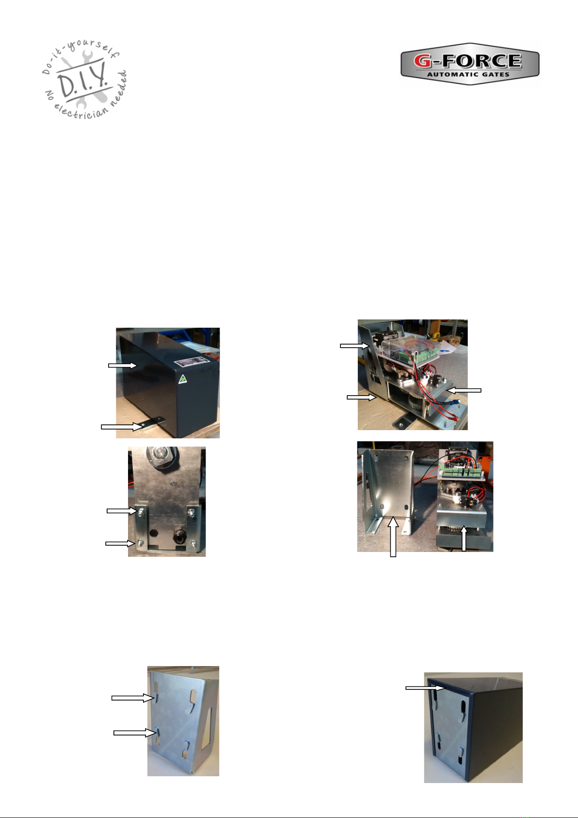
Place the complete motor on a work bench. Remove the black steel motor cover. Take note or a
photo detailing how the gate motor is assembled and the circuit board wiring for possible future
reference.
Separate the drive assembly and circuit board from the gate motor mounting cradle by
undoing the 4 nuts underneath the motor holding the drive assembly in the mounting cradle and
remove the drive assembly and circuit board from the gate motor mounting cradle. Take care not
to damage the circuit board or allow it to get wet.
AG5 DC2 GATE MOTOR
INSTALLATION AND SET UP
INSTRUCTIONS
Complete
Motor
Assembly
without cover
Undo the 4
nuts
underneath
the motor.
Mounting Cradle Drive Assembly
with Circuit Board
Mounting Cradle
Motor Cover
Drive Arm
Undo 4 nuts
underneath gate
motor to remove
Motor assembly.
Ensure the lip
of the motor
cover correctly
fitted over the
mounting cradle.
4 Spacer
Tabs.
Check the 4 spacer tabs are in place on the back of the mounting cradle. If the spacer tab has fallen off
then attach it with silicon otherwise use packing washers to replace the spacer tab. The spacer tabs allow
the lip of the motor cover to be correctly fitted over the mounting cradle.

© 2012 G Force Automac Gates All Rights Reserved
Mounting the Gate Motor (con’t)
Loosely attach the mechanical latch swing arm bracket to the bottom rail of the farm gate
approximately 800mm to 900mm from the inside of the hinge post and tighten by hand.
Place a spirit level (or a straight piece of wood with a small spirit level), on the top of the arm
bracket, level off the spirit level and mark the post on the underside of the spirit level. Measure
upwards 20mm from this mark and draw a straight line. Place the bottom edge of the mounting
cradle on this line and mark and drill the mounting holes or use the mounting template included
in these instructions. Firmly attach the mounting cradle to the post and check that the cradle is
level. Fit the drive assembly into the cradle. Ensure the washers are in place and fully tighten the
4 nuts to firmly secure the drive assembly in the mounting cradle. Remove the mechanical latch
swing arm bracket from the gate.
AG5 DC2 GATE MOTOR
INSTALLATION AND SET UP
INSTRUCTIONS
Mechanical Latch Swing
Arm Bracket.
Spirit Level
Mark post on the
underside of level then
measure up 20mm and
draw a straight line.
Place the bottom edge of the
mounting cradle on this line
and mark and drill the
mounting holes. Firmly fit
mounting cradle and ensure it
is level.
Fit the drive assembly into the
cradle. Ensure the washers are
in place and fully tighten the 4
nuts to firmly secure the drive
assembly in the mounting
cradle.
Swing
Arm
Loosely
attach
Mechanical
Latch Swing
Arm Bracket
to gate.
Mechanical
Latch Swing Arm
Bracket with
Brass Olive, Bolt
and Nut
Spirit Level

© 2012 G Force Automac Gates All Rights Reserved
Attaching the Arms and Brackets to the Gate
FOR OUTWARD OPENING GATES REFER TO THE SPECIAL INSTRUCTION SHEET
Refer to the “Internal Manual Release” instructions on page 5. Disengage the motor gear by
loosening the internal release bolt and push the DC motor away from the gearing. The motor
drive arm should now be free to rotate by hand.
Move the gate into the closed position manually.
Fit the swing arm assembly to the drive arm. Loosely attach the mechanical latch arm bracket t0
the other end of the swing arm assembly.
Extend the swing arm straight out and mark a position where the mechanical latch arm bracket
touches the gate. Ensure the swing arm is at the end of the slot furthest from the gate motor.
Measure approximately 40mm back towards the gate motor from the marked position and attach
the mechanical latch swing arm bracket or standard gate bracket to the gate at this point.
Tighten the two swing arm bolts with care not to over tighten. Open and close the gate manually
by hand several times to test.
Swing Arm Bolt
The Safety Swing Arm
Assembly should be
installed as shown here
Mechanical Latch Gate Bracket.
Ensure the swing arm is at the
end of the slot furthest from the
gate motor
AG DC2 GATE MOTOR
INSTALLATION AND SET UP
INSTRUCTIONS
Attach the mechanical latch gate bracket ( to the
end of swing arm using brass olive, bolt and nut.
Ensure the bolt is in the slot.
Swing Arm Drive Arm
Screw the two 12mm bolts with lock washers
(not shown) to attach Swing Arm to the Drive
Arm.
Swing Arm Bolt
Table des matières
Autres manuels G-Force ouvre-porte


