FunkTronic Major 4a Manuel utilisateur

Major 4a
Kompetent für Elektroniksysteme
English 2.0

m4a_eng2_0 (09.11.04)
- 2 -
Kompetent für Elektroniksysteme
m4a_eng2_0 (09.11.04) - 3 -
Kompetent für Elektroniksysteme
Technical Data
Order Information
Ord.-No. Description
681000 Major 4a
900012 Power Supply 230/12 Volt
Voltage of operation 12 V
Current max. 800 mA
Weight 1,5 kg
Dimensions (without gooseneck microphone) 245 x 220 x 95 mm
Input impedance 2/4-wire 600 Ohm
Output impedance 2/4-wire 600 Ohm
Delivery
Major 4a with handset and gooseneck microphone
Power plug
Power Supply not delivert with
Contents
Delivery 2
Order Information 2
Technical Data 2
Control Elements Major 4a 3
General features 3
Rearview Major 4a 4
Sockets pinout Major 4a 4
Connecting Major 4a (5a) --> Two-Way-Radio via multiwire 5
Connecting Major 4a (5a) --> Line Interface LIM-AC 5
Keypad layout in programming mode 6
Menu structure 6
Hardware con guration 9
2/4-wire con guration 9
2-wire con guration with FT630 9
Programming short call 10
Software con guration 10
Individual programming of the buttons 11
Permanent digits of encoder 12
Transmitting 6/7/8-tone 13
sequences 13
Channel scanning function 13
Reset to factory defaults 14
Sample con gurations Major 4a (5a) 15
Table of registers Major 4a 16
Release Notes 24

m4a_eng2_0 (09.11.04)
- 2 -
Kompetent für Elektroniksysteme
m4a_eng2_0 (09.11.04) - 3 -
Kompetent für Elektroniksysteme
Control Elements Major 4a
Handset
with PTT button
Gooseneck microphone
Loudspeaker button
Call button
Short call button PTT button
LC Display
Function buttons
Special buttons
Status LED´s
General features
The Major 4a is the newer design of the well kown Major 4. The Display was replaced by an alpha-
numeric LC Display with background illumination. A gooseneck microphone with high dynamics has
come to it. The programming possibilities were essentially widened and strongly simpli ed by clear
text menu structure.
There are two sockets for headsets. One is normaly used for a PTT foot button. The 7 digital outputs
are normaly used for channel switching or also other functions. For operation a 12 volt power supply
is necessary.
The Major 4a can be programmed via the serial interface or keypad. It is also possible to connect a
printer or terminal on the serial interface. For printers with parallel interface is an optionaly interface
available.
m4a_eng2_0 (09.11.04)
- 4 -
Kompetent für Elektroniksysteme
m4a_eng2_0 (09.11.04) - 5 -
Kompetent für Elektroniksysteme
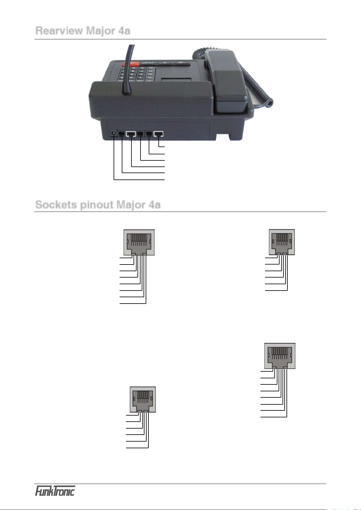
ST1 Radio socket ST = socket
ST2 Headset 1
ST2A Headset 2
ST3 Digital outputs
ST4 Serial interface RS232
PWR Power supply 12V, max. 1,5 A
inside positive, outside ground
Rearview Major 4a
Pinout Radio socket ST1,
rearview
AF input B 1
AF input A 2
Squelch input 3
GND 4
+12 V, max. 200 mA 5
Transmit active low 6
AF output A 7
AF output B 8
Pinout headset 1 + 2,
ST2 and ST2A
GND 1
GND ST2, AF mic. ST2A 2
AF earphone 3
GND earphone 4
GND ST2A, AF mic. ST2 5
PTT, active GND 6
Pinout ST3
digital in/outputs
OUT0 1
OUT1 2
OUT2 3
OUT3 4
OUT4 5
OUT5 6
OUT6 7
GND 8
Pinout
RS232 ST4
NC 1
NC 2
TxD 3
RxD 4
GND 5
NC 6
Sockets pinout Major 4a
All sockets shown from rear few.
All audio in/outputs equiped with transformers.
PIN 5 is for supply (+12V) of external devices
(LIM-AC, FT634C, FT633AC).
Attention, not for supply of radio, because of
only 200 mA output current.
To the RS232 socket you can connect a printer
for messages.
There are two sockets for connecting a headset.
One is for connecting headset, the other for use
of external PTT-Button.
The digital PINs are for use as in- or outputs. Most
they are used for remote control of channels.

m4a_eng2_0 (09.11.04)
- 4 -
Kompetent für Elektroniksysteme
m4a_eng2_0 (09.11.04) - 5 -
Kompetent für Elektroniksysteme
Connecting Major 4a (5a) --> Two-Way-Radio via multiwire
All audio in/outputs of Major 4a (5a) are equiped with transformers. No PINs are grounded, therefore
one must be connected to ground at the two-way-radio. We suggest to ground PIN 1 and 8 at the
radio.
PIN 5 is for supply (+12V) of external devices (LIM-AC, FT634C, FT633AC). Attention, not for
supply of radio, because of only 200 mA output current.
Connecting Major 4a (5a) --> Line Interface LIM-AC
The line interface LIM-AC is simply connected via a 8-wire patch cable (like used for ethernet) to the
Major 4a (5a).

m4a_eng2_0 (09.11.04)
- 6 -
Kompetent für Elektroniksysteme
m4a_eng2_0 (09.11.04) - 7 -
Kompetent für Elektroniksysteme
Menu structure
Simultaneous pressing of the * button and the # button you get into the menu. With the but-
ton you switch to the next menu point. With the button the selected menu point is activated.
- put in the register you want
to program
- with 222 the factory default
values are programmed
- overwrite the Code with
your values
= escape menu without
change
= store value, escape
menu
1 = Input level
2 = Output level
3 = Gooseneck
microphone level
4 = Handset microphone
level
5 = Headset microphone
level
6 = DTMF output level
* simultaneously #
È
ÆÆ
È È È
- displayed for 3 seconds
- the adjustment area of the
Pots is 0-63
- input direct via the keypad
or
= value increment
= value decrement
= escape menu without
change
= store value, escape
menu
Keypad layout in programming mode
The button decrements and the button increments.
The buttons S1 to S4, the * button and the # button are
concerned with A to F.
¡13
5
4
8
2
0
9
*
7
6
#
A
EF
+
-
S1
¡
B
S2
¡
C
S3
¡
D
S4
Software version : F4
Next menu : F3
Level settings : F4
Next menu : F3
Software: Major 4a V1.24
Date : 23.09.04
Poti-Nr. (1-6):
select number:
EEPROM programming : F4
Next menu : F3
Register:
Register: 000
Code 12345

m4a_eng2_0 (09.11.04)
- 6 -
Kompetent für Elektroniksysteme
m4a_eng2_0 (09.11.04) - 7 -
Kompetent für Elektroniksysteme
0 = 200 Hz
1 = 300 Hz
2 = 400 Hz
3 = 600 Hz
4 = 800 Hz
5 = 1000 Hz
6 = 1600 Hz
7 = 2400 Hz
8 = 3400 Hz
9 = 4000 Hz
S1 = 2900 Hz
S2 = 3000 Hz
S3 = 3100 Hz
S4 = 3300 Hz
* = 1200 Hz
# = 1800 Hz
* simultaneously #
È
Continuation
ÆÆÆ
È
Æ
È
= decrement contrast
= increment contrast
= escape menu without
change
= store value, escape
menu
È
Æ
= one digit left
= one digit right
= escape menu without
change
= store value, escape
menu
Put in the values you want
with the keypad 0 to 9.
Menu structure
= escape menu
select number:
Transmit test tone : F4
Next menu : F3
Change frequency 0.....C
F3 for ESC Hz
Adjust contrast : F4
Next menu : F3
Displaycontrast: 90
F1- F2+ F3ESC F4STORE
Set date/time : F4
Next menu : F3
15.10.04 22:47:01

m4a_eng2_0 (09.11.04)
- 8 -
Kompetent für Elektroniksysteme
m4a_eng2_0 (09.11.04) - 9 -
Kompetent für Elektroniksysteme
The clock is already adjus-
ted in factory. Note down
the values for digital and
analog before changing.
Biger values accelerate and
smaller values slows down
the clock.
Change in digital makes
more alteration then in ana-
log. Fine adjustment should
be done in analog, step by
step.
* simultaneously #
È
ÆÆÆ
È
Æ
ÆÆÆ
= one digit left
= one digit right
Menu structure
Continuation
= escape menu without
change
= store value, escape
menu
- displayed for 3 seconds
È
select number:
Adjust clock : F4
Next menu : F3
Digital (0-6) : 3
Analog (00-59): 29
Serial number : F4
Next menu : F3
Serial number: 1111-22
Mainboard : FFFF/FF

m4a_eng2_0 (09.11.04)
- 8 -
Kompetent für Elektroniksysteme
m4a_eng2_0 (09.11.04) - 9 -
Kompetent für Elektroniksysteme
Hardware con guration
The Major 4a (5a) is for use on 2- or 4-wire line. For 2-wire line jumper 1 have to be set. Remove
jumper 1 for 4-wire line.
2/4-wire con guration
2-wire con guration with FT630
For remote control of radio over longer distance it is adviceable to use a 2-wire line with the FT630.
The FT630 transmitts and receives the PTT and SQUELCH state via DC.
If there is no DC way on the line or also remote channel control necessary, we suggest to use FT634C
or FT633AC.

m4a_eng2_0 (09.11.04)
- 10 -
Kompetent für Elektroniksysteme
m4a_eng2_0 (09.11.04) - 11 -
Kompetent für Elektroniksysteme
The digits in register 174 activates the following
functions:
1. digit = 2 --> function 2 - transmit call
sequence
2. digit = 2 --> short call
3. digit = F --> input necessary
4. digit = 0 --> 5 tone sequence
5. digit = 1 --> not applicable
Follow next steps to view or change the values in
register 174 and 175.
Software con guration
Programming short call
The example below shows the programming of
short call 1 in register 001 with tone sequence
12345.
0
È
0
1
È
È
The line „Code“ shows the current programming.
Overwrite with your values.
Key F3 escapes without any changes.
Key F4 stores the displayed values.
Each button of the Major 4a can be programmed
with any function. Register 174 and 175 has to
be programmed with the appropriate values of the
short call button (Z-Button).
Register 174 is for the function after short
activation of Z-Button and register 175 after
longer activation.
Register 174 is coded with 22F01 and register
175 with 00000.
The leading zero in register 175 disables action
after long pushing Z-Button.
1
È
7 4
È
È
È
È
È
Register: 174
EEPROM programmed
Register:
Funk Tronic Major 4a
select number:
EEPROM programming : F4
Next menu : F3
Register:
Register: 001
Code 12345
select number:
EEPROM programming : F4
Next menu : F3
Register:
Register: 174
Code 12345
select number:
* simultaneously #
* simultaneously #
Autres manuels pour Major 4a
4
Autres manuels FunkTronic Microphone


