Fultz Pumps SP-400 Manuel utilisateur

30 DAY LIMITED FACTORY WARRANTY
FULTZ PUMPS, INC. sampling pump units are warranteed to be free from defects in
material and/or workmanship for a period of thirty (30) days from date of shipment.
The pump head is warranteed to be free from defects in material and/or workmanship
for one (1) year from date of shipment. All requests for warranty service must be
received during the warranty period. Should any unit fail during the warranty period
due to faulty material and/or workmanship, it will be repaired at the factory or
replaced at the option of Fultz Pumps, Inc. All units returned for any warranty claim
must obtain prior factory authorization and shall be shipped freight prepaid. COD
shipments WILL NOT be accepted. The liability of Fultz Pumps, Inc. is limited
exclusively to repair or replacement of defective units. Under no circumstances shall
Fultz Pumps, Inc. be liable for consequential damages of any kind. It shall be the
user’s responsibility to insure the suitability of the unit for any intended use, purpose,
or application. In addition, the following items not covered by this warranty shall
include but are not limited to:
-Expendable items such as rotors, tubing, etc.
-Damage due to misuse, carelessness, abuse,
accidents, negligence, corrosion, etc.
-Suitability for specific purpose, use or application.
-Any alteration of any kind.
-Unauthorized repair.
This represents the total of all responsibilities obligated by this warranty.
1

FOREWORD
The information presented in this instruction manual has been compiled to
provide the operator with a thorough understanding of the capabilities and
operation of the unit. It is strongly recommended that this manual be read
carefully with all cautions noted and observed before placing the equipment
in service.
Every effort has been made to make operation of the unit as simple, reliable,
and trouble free as possible. Should a malfunction occur, consult the
troubleshooting chart for possible causes and/or corrective measures. If the
problem persists, call or write the service department at:
FULTZ PUMPS, INC.
P.O. BOX 550
LEWISTOWN, PA 17044
USA
PHONE 717-248-2300
FAX 717-248-5458
e-mail [email protected]
It may be possible to diagnose minor problems over the phone, however if it
should be necessary to return equipment to the factory for service, please
follow the shipping instructions provided by the service department.
2

TABLE OF CONTENTS
INTRODUCTION 4
PUMPHEAD 5
CONTROLPANEL 6
HOSE REEL 8
HOSE 8
FRAME 9
POWER SUPPLY OPTIONS 9
TESTING THE PUMP (IN-HOUSE) 11
FIELDUSE 12
MAINTENANCE 13
TROUBLESHOOTING 14
PUMP DIAGRAM 15
WARRANTY INFORMATION 17
3

INTRODUCTION
The Fultz Pumps, Inc. line of sampling pump systems have been developed to
provide field personnel with a compact portable, self contained unit for the
convenient collection of samples from groundwater monitoring wells or similar
devices.
4

PUMP HEAD
The Fultz Pump Inc. line of pumps operate on the principle of positive displacement.
Water is introduced into the pump through a 60 mesh screen into a stainless steel
cavity. Two Teflon* gears or “rotors” inside the cavity displace the water up through
the hose in a steady stream. Teflon* is used in the interest of purity, however this is
the wear item on the pump head and the only thing to require routine maintenance.
Rotors are field replaceable, approximately 100 hours of pumping time can be
expected from a set of rotors in clear water, however suspended solids will affect the
life of these rotors. We recommend the operator always keep a spare set of new
rotors on hand. The pump’s electric motor runs on 36V DC power. The pump head
specifications are as follows:
SP-400 Pump Head
Diameter: 1.75”
Length: 9.16”
Weight: 2.5 lbs.
Materials: 304 Stainless Steel
Teflon*rotors
Viton housing seal
Carbon motor seal
Performance: 1.4 GPM @150’
*Teflon is a registered trademark of E.I. DuPont.
5
CONTROL PANEL
Forward/Off/Reverse Switch - This 3 way switch is used to select which direction the
pump is running or turn the power off to the pump. Reverse is only to be used
momentarily to clear any debris that may have collected around the pump’s screen
during purging/sampling, or to drain the hose once purging/sampling is completed.
Always turn power off before changing direction of pump or damage to the unit
may result
Amp Meter - Displays the amperage drawn by the pump. The model SP-300 and SP-400
pumps should draw between 3.5 and 4.5 amps. If the meter is reading 5+ amps, turn
the power off and refer to troubleshooting guide or call Fultz Pumps, Inc. for
assistance.
Breaker Switch - Installed to protect the pump motor. Should the pump encounter
any difficulty pumping and draw 5+ amps, the breaker switch will turn the system off.
The switch is normally black, however if it is activated, the lower section will be
white. If this should happen, wait 2 minutes for the system to cool and press the
switch back down again to initialize. Refer to the trouble-shooting guide to find out
what may have caused the pump to draw high amperage. Never try to override the
breaker switch by holding it down.
6

DC Plug - This jack is for an optional 36V DC battery pack \
Power In / AC or DC - This switch is to select between using the internal AC power
supply or an external DC battery source plugged into the DC jack.
Flow Rate Knob - Controls the pumping speed. This is convenient when changing from
high flow rate for purging to lower flow rates for sampling. Use caution when slowing
the flow rate down so as not to stall the pump and cause the motor to burn up. If the
pump should stall, the amp meter will jump about 1/3 amp. The best way to avoid
this is to not stop the flow entirely. Always start the pump with the flow rate set to
full speed.
7

HOSE REEL
A composite hose reel is supplied with the rotating reel model. Reel
capacity is 200’ of polyethylene hose or 300’ of Teflon* hose. Brass slip
rings in the hub of the reel allow the pump to be run while raising or
lowering the pump depth or locked into a stationary position. The
hose/reel assembly can easily be removed should the operator wish to
change hoses. To remove the hose/reel assembly, use a snap ring tool
to remove the snap ring on the hub of the reel. Slide the gray PVC
spacer off the hub (be careful not to loose the spacer). Slide the
hose/reel off.
HOSE
The hose with integrated wire is both easy to handle, and easy to
decon. This hose is available in both polyethylene and Teflon* lined
polyethylene. Standard hose length is 100’, however hoses can be
made to any length specified. Extension hoses can also ordered to any
length. Quick connect couplings made of stainless steel and pvc
watertight electrical connections are installed.
* Teflon is a registered trademark of E.I. DuPont.
8

FRAME
The freestanding tubular frame is designed so one person can easily and
comfortable lift and transport the unit.
POWER SUPPLY OPTIONS
A.
A. Battery Pack - 24V and 36V Battery packs are equipped with gelled electrolyte
batteries. This allows the batteries to be shipped and stored in any position without
spillage of corrosive materials. Batteries should not be totally discharged before
charging or they may refuse to accept a charge. Charge when performance begins to
fade and also before putting battery pack into storage. Charge only with the charger
supplied with the unit. The operator can expect 3-4 hours of pumping time before
batteries need charged overnight (approximately 16 hours). Avoid leaving batteries on
the charger for an extended time. The batteries do not develop a full storage
capacity until after approximately 25 charge/discharge cycles have been completed.
If the above cautions are followed, the operator can expect 250 to 500 cycles from
these batteries.
9

B. C. D. E.
B. 110V Power Supply - Inputs 110V AC and outputs 36V DC required to run the pump.
Use this with any 110V power source (110V generator, 110V wall outlet, etc.) No
maintenance is required for this power supply.
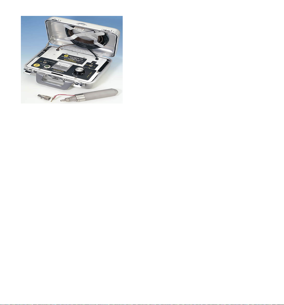
C. Portable Power Supply Control Case - This briefcase also inputs 110V AC and
outputs the 36V DC required to run the pump. Use with any 110V power source (110V
generator, 110V wall outlet, etc.)or plug a 36V Battery Pack into the DC jack. No
maintenance is required for this power supply.
D. 110V Stand Alone Power Supply Control Box -inputs 110V AC and outputs the 36V
DC required to run the pump. Use with any 110V power source (110V generator, 110V
wall outlet, etc.) No maintenance is required for this power supply.
E. 12V Power Supply - For use when powering the pump system from an automobile
battery. Attach the alligator clips to the vehicle’s battery terminals (be sure to match
polarity). Use an extension cord (<50’ recommended) to go from the vehicle battery
to the well head. Plug one of the other power supplies (B, C, or D above) into the
extension cord. Be sure the cooling fan on this unit is exposed.
10
Table des matières
Manuels Pompe à eau populaires d'autres marques


Sykes AmeriPumps
Sykes AmeriPumps GP100M Guide de dépannage

DUROMAX
DUROMAX XP WX Series Manuel utilisateur

BRINKMANN PUMPS
BRINKMANN PUMPS SBF550 Manuel utilisateur

Franklin Electric
Franklin Electric IPS Manuel utilisateur

Xylem
Xylem e-1532 Series Manuel utilisateur

Milton Roy
Milton Roy PRIMEROYAL Manuel utilisateur