Fuelab 20106 Manuel utilisateur
147220126, No Rev Sheet 1 of 14
Model Number 20106
2005-2013 Dodge Cummins® 200 Installation Kit
Operating and Installation Instructions
C
CA
AU
UT
TI
IO
ON
N!
!
This product is to be installed only by persons knowledgeable in the repair and modification of vehicle fuel systems
and general vehicle systems modification. Only a qualified technician or mechanic who is aware of applicable
safety procedures should perform the installation of this product.
GASOLINE AND OTHER FUELS ARE FLAMMABLE AND CAN BE EXPLOSIVE!
Perform the installation in a well ventilated location only to minimize the build up of fuel vapors. NO open flames,
smoking or other sources of ignition are to be present during installation, to prevent fire or explosion that can cause
serious injury or death. Grinding, cutting, and drilling must be performed with care to prevent ignition. Draining and
removal of all fuel and ventilation of vapors in vehicle and fuel system is recommended when performing such
procedures. Proper eye and personal protection is required at all times during installation.
W
WA
AR
RN
NI
IN
NG
G!
!
The Vehicle’s fuel system may be under pressure! Do not loosen any fuel connections until relieving all fuel system
pressure. Consult an applicable service manual for instructions to relieve fuel system pressure safely.
Application:
This Installation Kit is intended to work with Fuelab® Velocity Series 200 Fuel System, Model 30303. Consult
instructions included with Fuelab® Velocity Series 200 Fuel System, to complete this set of instructions pertaining to
the use of this Installation Kit. This Installation Kit is also intended to be used for replacement of OEM lift pump
systems that are originally installed on vehicle. This kit applies to Dodge Cummins® Diesel Vehicles, between and
including the years of 2005-2013. If this Kit is not correct, please contact your Fuelab® distributor immediately for
replacement or selection of an appropriate Installation Kit.
Product Contents:
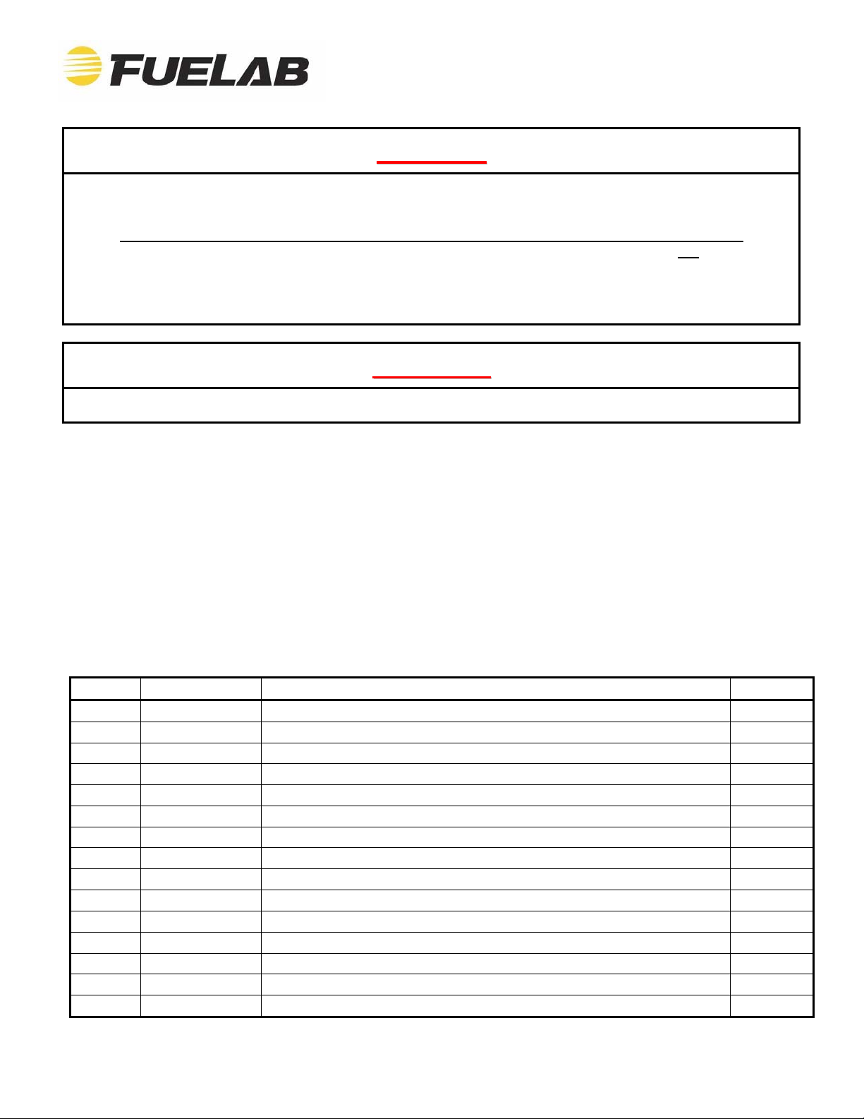
Verify the contents of this box, against list of components below and on the next sheet, to ensure that nothing is
missing. Contact your Fuelab® distributor immediately for replacement. You may have extra parts left over after
installation since Fuelab® has included extra parts for all years of the application described. While this kit is
designed for designated vehicles, vehicle manufacturers routinely change production components, even during the
same production year. Please contact Fuelab® if the particular vehicle has different descriptions or components
that are incompatible as described within these instructions.
ITEM P/N Description Qty
1 FL500 Fuel Line, 1/2” , Superflex 15’
2 FL375 Fuel Line, 3/8” , Superflex 7’
3 PORB108 10 ORB x 1/2" Push-lok® adapter, Steel 1
4 PORB88 08 ORB x 1/2" Push-lok® adapter, Steel 1
5 PORB86 08 ORB x 3/8" Push-lok® adapter, Steel 1
6 M1208 12mm x 08 MJIC adapter w/seal 1
7 POE8 Push-lok® elbow, 1/2" 1
8 QC375 3/8” QC for return 1
9 WCL500 Clamp for Inlet Straining Filter 2
10 WCL375 Clamp for return connection 1
11 CBT6 Cable Ties, Nylon 5" 6
12 551770 Inlet Straining Filter 1
13 EPH17-3 Extended pump harness 1
14 DTK2 Draw Tube Kit 1/2" Push-lok® 1
16 CWRAP Convoluted Plastic Wire Harness Wrap 11'
2
8
4
14
6
13
1 3
12 10
7
16
2x 9
6x 11
5
147220126, No Rev Sheet 2 of 14
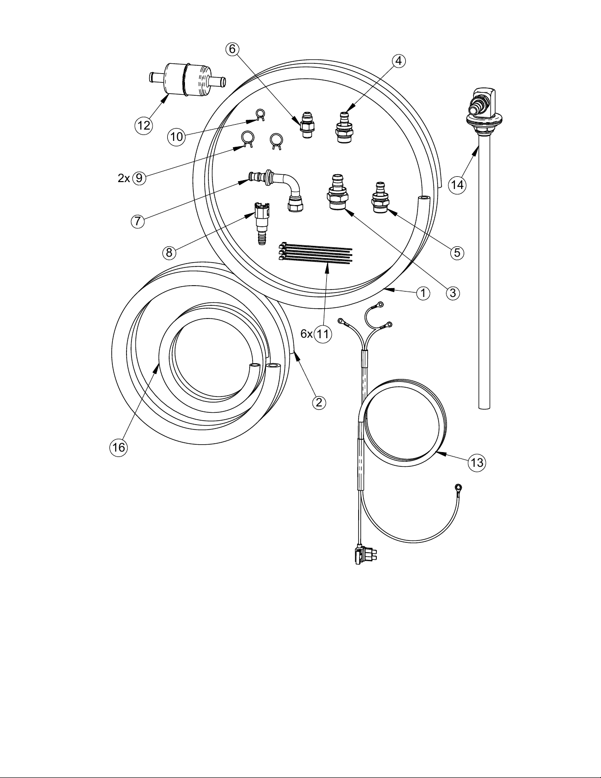
Check above photo and list shown on previous page, to ensure no components are missing or
damaged. Contact your Fuelab® distributor immediately for replacement.
Some items listed in these instructions are included in Lift Pump / Filtration
System, sold separately (reference sheet 1, under Application).
FOLLOW ALL INSTRUCTIONS HEREIN AS WELL AS INSTRUCTIONS
INCLUDED WITH THE LIFT PUMP / FILTRATION SYSTEM. BOTH SETS OF
INSTRUCTIONS CONTAIN IMPORTANT INFORMATION!
147220126, No Rev Sheet 3 of 14
The most difficult step of the installation procedure is removing the vehicle’s fuel tank (this step may not be required
for all vehicles). With very little room between the top of the fuel tank and the Bed of the vehicle, it may be difficult
to get the fuel lines disconnected. Make sure that the fuel tank is as empty as possible. Even at approximately
1/8th of a tank of fuel, a substantial amount of fuel is still inside. Drain as much as possible! The installation may
also be performed with the Bed of the vehicle removed, without the requirement of tank removal. If the tank
requires drilling during modification however, the fuel tank MUST be removed from the vehicle and completely
drained of ALL FUEL. For fuel connections using pipe threaded fasteners (tapered threads or non o-ring or flare
connections), use Teflon® tape. On connections using Tapered Ends, or Fittings using O-rings, DO NOT use
Teflon® tape.
In addition to typical professional automotive tools, items you may want to ease the installation, that are not
included with this Installation Kit are:
Heat gun or hair dryer and a small amount of oil, to lube the fittings and soften the fuel line for the Push-
lok® fittings. Additional items that would be helpful include box cutter or shears for the fuel lines and an air
source to blow out all the fittings and hoses. A few extra small to medium size hose clamps can also help
(DO NOT over-tighten worm gear style clamps) as well as additional Cable Ties.
Step 1: Inventory all of your parts with the included packing list. Lay out the parts to verify that everything is
included (see diagram on previous sheet as well as Contents List on the first sheet). Also inventory and lay out all
parts of the Lift Pump / Filtration System (sold separately, shown below – Reference Model 30301).
The System Bracket (item S2) attaches to the Lift Pump / Filtration System (item S1) as shown below. Fuelab®
recommends attaching the System Bracket to Lift Pump / Filtration System after System Bracket is installed on
Front Rail Bracket (item S3, and see next step) for ease of assembly. Dry-fitting your system with rail brackets
(explosion view available in companion instructions) is recommended first, to ensure desired bracket adjustment,
prior to final assembly.
Make sure to USE Loctite® 242 thread adhesive (item S14) on the Captive Studs (items S6) and Acorn Nuts (items
S9), prior to final assembly. If the supplied thread adhesive is not used, then unit can vibrate and loosen over time.
The thread adhesive is supplied with Lift Pump / Filtration System. Location for Locktite® use during the final
assembly is highlighted in the companion instructions (instructions for Model 30303).
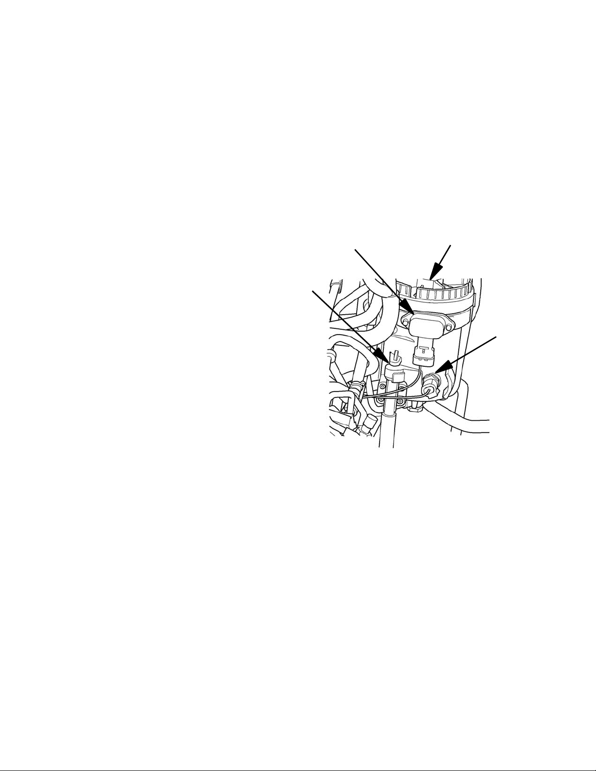
147220126, Rev A Sheet 4 of 14
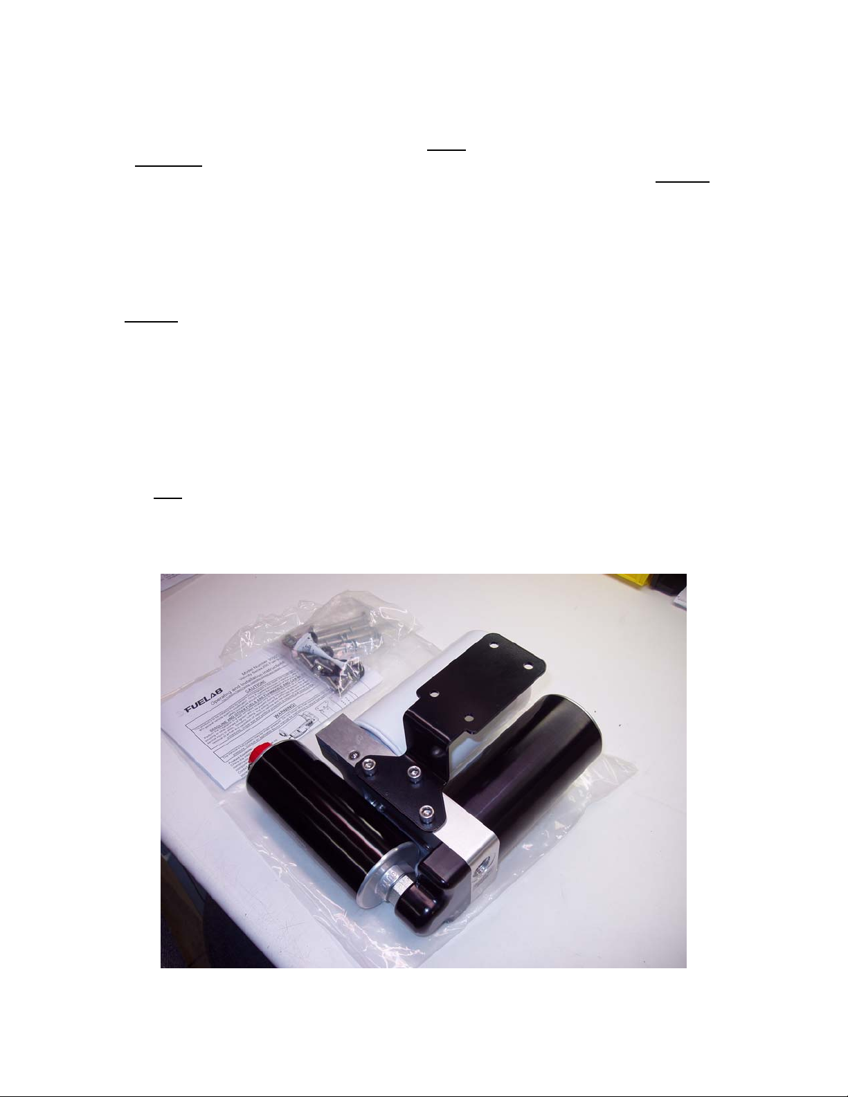
OEM FUEL
FILTER
HOUSING
2005-2013 DODGE CUMMINS TRUCKS, USING CP3 INJECTION PUMP
OEM FUEL
LIFT PUMP
LIFT PUMP ELECTRICAL
CONNECTOR (NEAR
OEM LIFT PUMP)
FUEL
DRAIN
HOSE
FUEL
DRAIN
VALVE
CP3
INJECTION
PUMP
INJECTION PUMP
INLET LINE AND
BANJO CONNECTION
Getting to Know the Vehicle
Dodge Cummins Trucks of this era can have several modifications performed to the fuel system. Inherent
shortcomings to the original lift pump system have prompted most of these vehicles to be modified. Dealers have
typically "upgraded" the fuel systems of these vehicles when in service, particularly when serviced for Injection
Pump failure. These failures are generally caused by a fuel supply failure (failure of the lift pump system), that
does not provide adequate pressure to protect the Injection Pump. The modification that is typically performed in
these cases is to remove the original lift pump and replace it with an adapter fitting (Original Lift Pump is typically
attached to the Filter Housing). Additional modifications includes the replacement of the Fuel Module (within the
fuel tank) that includes an in-tank fuel pump (the original Module, when an external lift pump is used, has no pump
inside). While this modification is an improvement over the original design, aftermarket lift pump systems entered
the marketplace to improve upon lift pump performance and filtration capability.
Inspect the vehicle's fuel system against the diagrams to determine the actual fuel system configuration, as this will
vary from vehicle to vehicle. Look for a possible aftermarket lift pump and /or filtration system along the frame rails,
near the transmission and fuel tank (some of these systems also include blue fuel hose that can help identify the
system). Many of these systems can include the addition of one or more filters similar in appearance to the filter
used on the Fuelab Model 30301 Fuel System (companion fuel system for this installation kit). Some other
modifications to the fuel system can also include the removal of the OEM Filter housing as well as the removal of
the OEM Lift Pump. Reference the appropriate diagram below and next sheet, to help determine the vehicle's fuel
system configuration.
147220126, No Rev Sheet 5 of 14
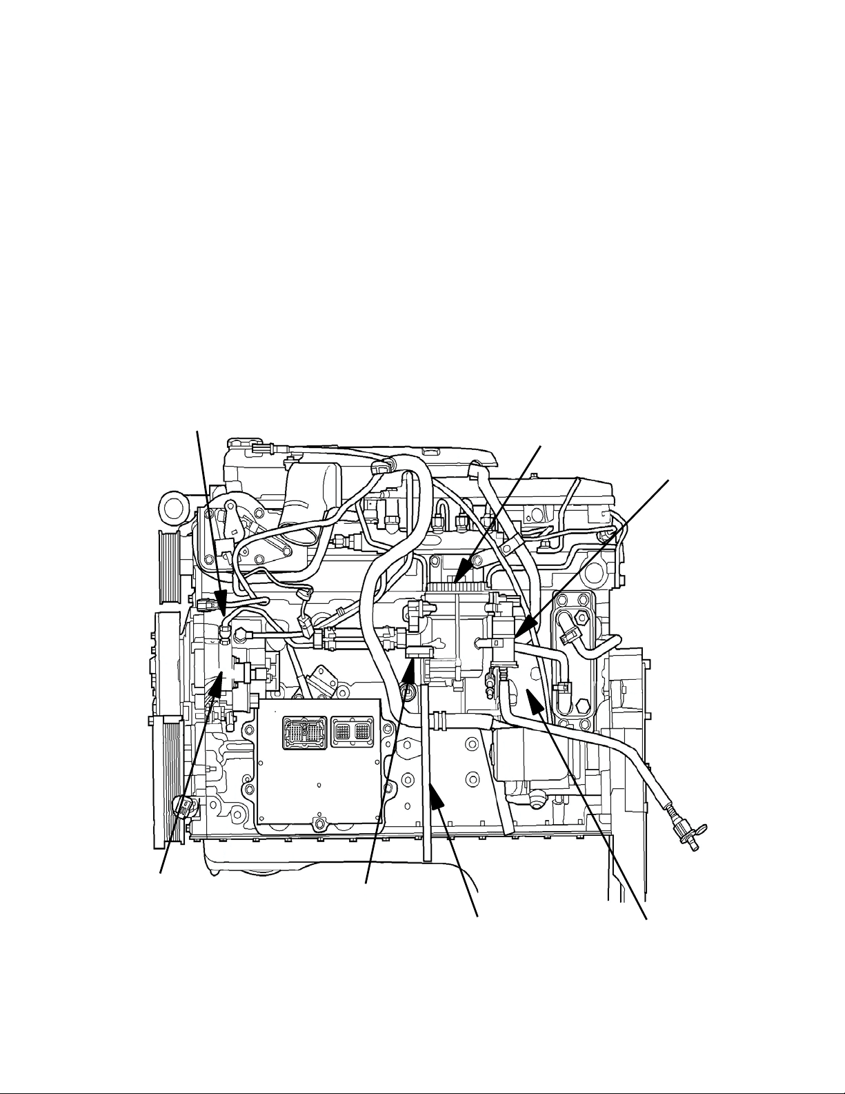
OEM FUEL
FILTER
HOUSING
FUEL HEATER
AND
THERMOSTAT
FUEL
DRAIN
VALVE
WATER
IN FUEL
SENSOR
OEM FUEL FILTER HOUSING FEATURES
Your vehicle may have other modifications to the fuel system as well. Double check for the correct Injection Pump
as well, by comparing the general look of the pump to these included diagrams. Use the following checklist during
inspection to understand the vehicle's current fuel system configuration:
• Correct Injection Pump? CP3
• Lift Pump Configuration? External (attached to OEM Filter), External Aftermarket or In-Tank
• Filtration Configuration? OEM Filter Housing, Aftermarket or Both
Installation Options
This installation kit offers an ability to quickly and effectively install a lift pump / filtration system that far exceeds
OEM standards in performance and reliability. This installation kit allows the use of the OEM Filter Housing (in
addition to the filters supplied with the Fuelab Model 30301 Lift Pump / Filtration System (Sold Separately). Some
vehicle owners have different desires regarding the continued use of the OEM Filter Housing. Keeping the OEM
Filter Housing in place has the following advantages:
• Retains OEM Fuel Heater (to improve cold climate
performance)
• Retains OEM Water in Fuel (WIF) Sensor
• Retains OEM Fuel Drain
• Redundant Filter
• Faster installation
Filter Housing in place can have the following disadvantages:
• Extra pressure drop under high flow conditions.
See the figure (right) labeling key OEM Filter Housing features.
147220126, No Rev Sheet 6 of 14
Step 2: Disconnect the Vehicle's Battery (or batteries, as diesel trucks typically have more than one) by
disconnecting the Negative or Ground Terminal(s) of each Battery to disable the Vehicle's Electrical System.
Step 3: Loosely attach the System Bracket (item S2) and bushings (items S7) to the Front Rail Bracket (item S3),
using the four (4) Captive Studs (items S6), Stud Washers (items S8) and Acorn Nuts (items S9). Follow the
companion instructions for proper assembly orientation. For convenience, the Wiring Harness (item 10) can be
attached to the Lift Pump / Filtration System, prior to final installation (reference Step 11, of these instructions). Be
sure to note proper wiring polarity, otherwise permanent damage to Lift Pump will result.
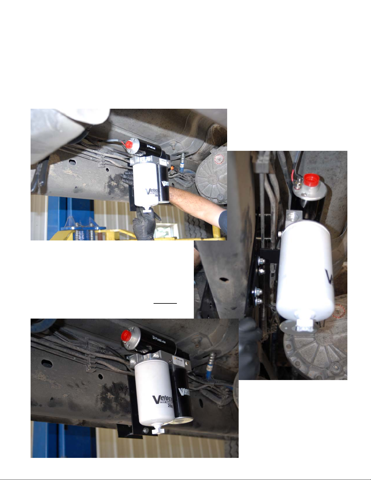
Step 4: Find a suitable place to mount the Lift Pump / Filtration System. On a short bed truck, the space is very
tight. The Lift Pump / Filtration System normally mounts on the inside of the vehicle’s frame.
Placing the Lift Pump / Filtration System into position as
a dry-fit (such that the thread adhesive is not being used,
and the fasteners are loose) can be helpful, to determine
the desired adjustment position of the bracket system as
well as determining the desired placement along the
vehicle’s frame. Multiple height positions are possible by
attaching the System Bracket through using the different
hardware positions of the Front Rail Bracket. DO NOT
position to where the Lift Pump / Filtration System can
rub against the cab body.
147220126, No Rev Sheet 7 of 14
Step 5: Loosen the hose clamps on the filler tube and the over flow tube to the fuel tank, located on the inside of
the fender well. Then loosen the 2 bolts that secure the tank strap until only a few threads are holding it up. Once
you have lowered the tank slightly, you must remove the electrical connector and the feed and return fuel lines on
top of the tank. For the fuel lines, use a pair of needle nose pliers, squeeze the tabs on either side and pull the fuel
line out.
Once the tank is lowered, remove the lock ring and remove the fuel tank module. Use caution not to bend or
damage the fuel tank level sender arm and sensor.
With the fuel tank removed, pour or pump out the remaining fuel from the tank before performing modifications. As
written in the CAUTION section on the first sheet of the instructions, removal of all the fuel is REQUIRED if drilling,
grinding or cutting is performed on the fuel tank itself, to prevent ignition or fire. Modification of the fuel tank itself is
not required, if modification to the fuel tank module is performed only. Removal of fuel from the fuel tank module is
REQUIRED.
Inspect the fuel tank module and its sealing gasket for cracks or damage. Replace components as necessary with
OEM replacement components if damaged components are found. Inspect all fuel lines and emission lines as well
as line disconnects for extreme brittleness, cracks or damage. Fuel lines must be replaced with fuel compatible
hose ONLY.
Step 6: Modifying the fuel tank module or fuel tank.
This Installation Kit and Instructions can allow modification of the fuel tank to install the Draw Tube Kit (item 14)
directly to the fuel tank instead of the fuel tank module. Modification of the fuel tank module is recommended, as
the fuel tank module acts as a baffle for the fuel, to reduce “fuel slosh” that can result in loss of fuel pressure at low
tank fuel levels, during braking or acceleration of the vehicle.
Fuel tank module’s appearance and design varies within different vehicle types and model years. Photos shown in
these instructions may appear differently than the vehicle being modified. General modification of the fuel tank
module is considered universal, although fuel line location, emission line location and fuel tank module
configuration may vary.
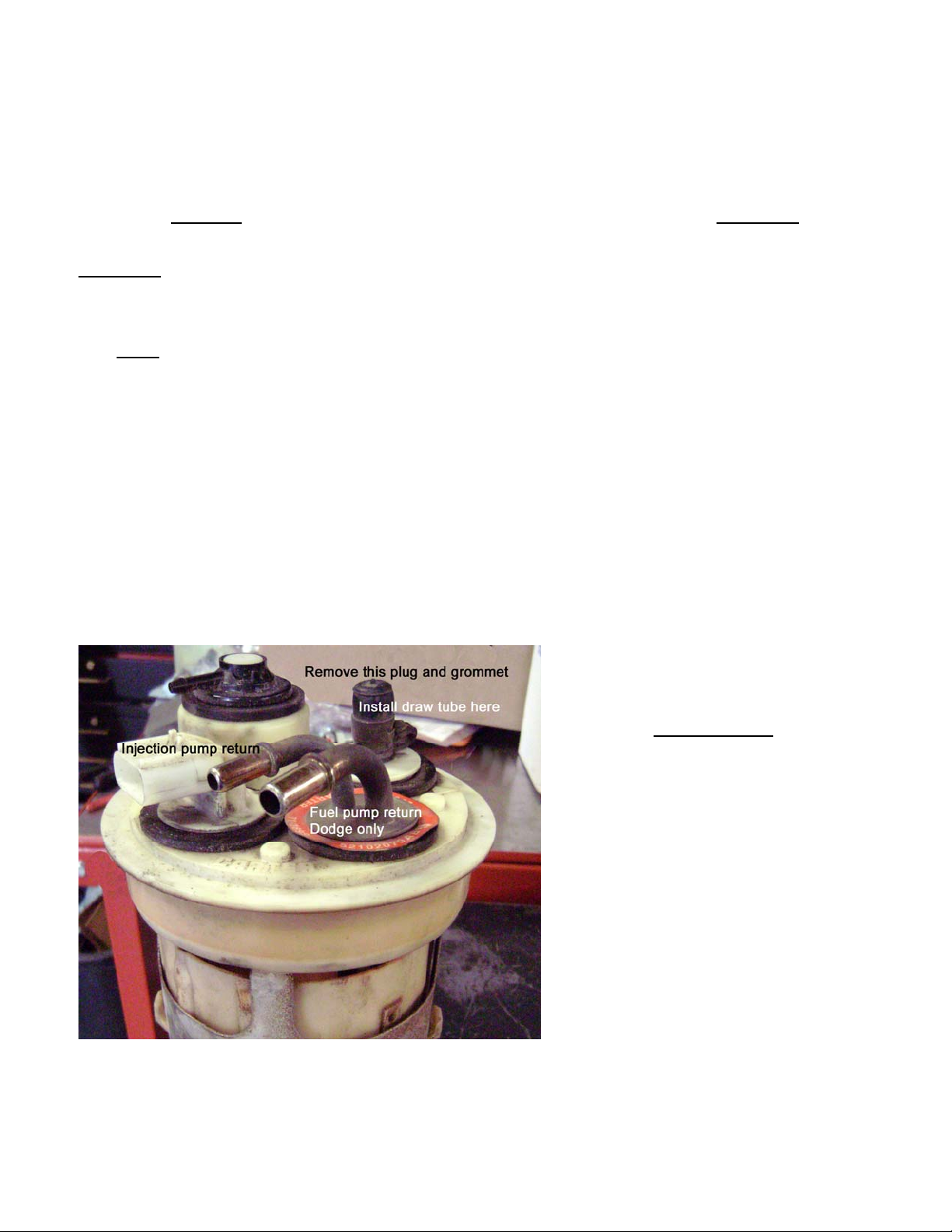
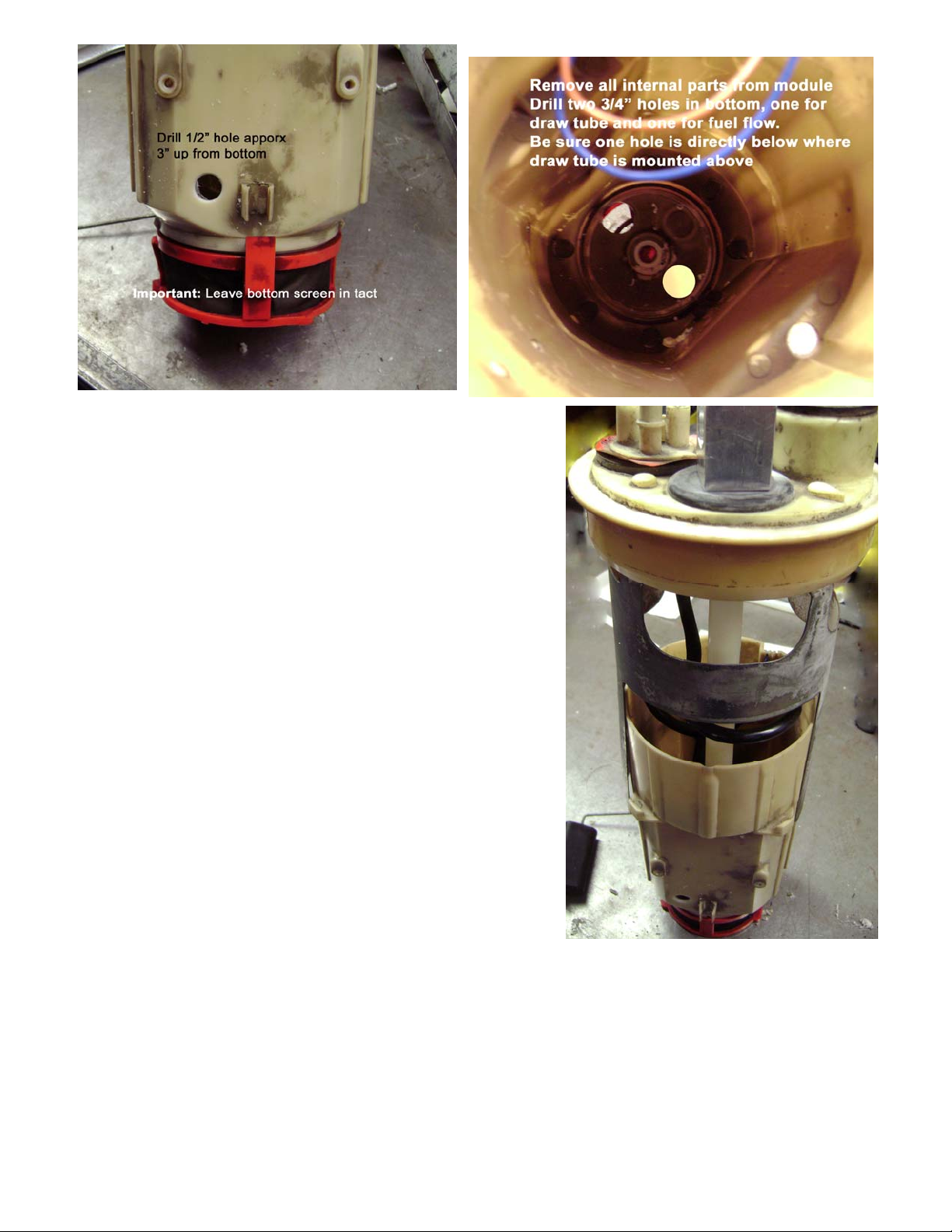
Locate a flat spot on top of the fuel tank module that is approximately 2” in diameter on top of the fuel tank module.
Some fuel tank modules have a plug installed (example in photo) that can be removed for this purpose. At this
location (centered), a 3/4” hole is to be drilled through the top to allow the installation of the Draw Tube Kit (item
14). Deburr hole, and inspect for cracks or splits. The plastic of the fuel tank module can be brittle, use caution
during all drilling.
SPECIAL NOTE:
The vehicle’s fuel tank module may appear
differently than as shown to the left, due to
various configurations produced over the
various models produced. The Draw Tube Kit
installation is considered universal.
147220126, No Rev Sheet 8 of 14
Due to variations of depth between various fuel tanks, the draw tube included in this kit (item 14) will have to be cut
to the correct length. If too much length is cut from the draw tube, then the vehicle will prematurely “run out of fuel”
while significant fuel still remains in tank. If the draw tube is too long, then the tube can be crushed upon
installation of the fuel tank.
To derive the correct length to cut from the end of the Draw Tube Kit (item 14), loosen and remove the locking nut
and washer from the Draw Tube Kit (item 14). The remaining rubber grommet and rubber washer should remain
on the Draw Tube Kit. Insert the draw tube into the fuel tank module, until it hits the bottom of the fuel tank module.
SPECIAL NOTE: Some fuel tank modules are spring loaded when inserted in the tank. Fuel tank modules such
as these that can change length, when inserted in the tank. Fuel tank modules in this configuration must
first be dry-fitted into the fuel tank prior to continuing, to ensure that the proper length of the draw tube is
determined. In cases such as this, it is important to remove the fuel from the tank, and support the fuel
tank along the outside of tank (or along straps) during this measurement procedure. This is done so that
the tank’s center is not pushed up during measurement (for higher accuracy).
Once the tube hits the bottom of the fuel tank module, a gap will form between the top of the fuel tank module and
the bottom of the rubber grommet of the Draw Tube Kit. Measure this gap and write it down. Add 1/4” to 3/8” to
this earlier measurement. Cut this calculated length of tube from the plastic tube portion of the Draw Tube Kit (item
14). This cut should be performed at an angle, to prevent the bottom of the fuel tank module from closing off fuel
flow, should the measurement be off, or fuel tank is later dented or tank shape is changed after tank installation.
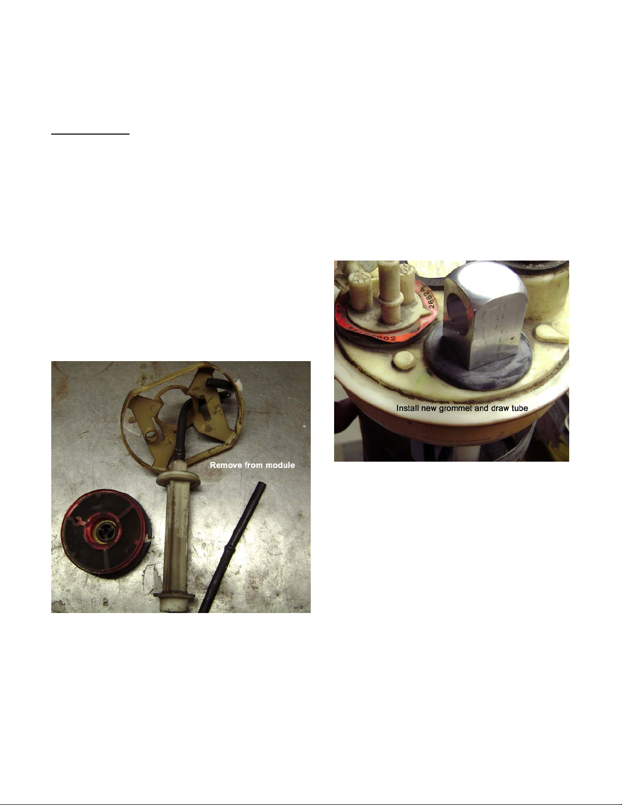
Remove fuel tank module from tank (if applicable) and
reinstall the modified Draw Tube Kit (item 14) back into the
fuel tank module. Re-install the kit washer and locking nut
back onto the threads of the Draw Tube Kit. Orientate the
outlet of the draw tube kit to point toward the same direction
as the original path of fuel lines. Tighten the nut until the
rubber grommet slightly compresses. See photo to right as
example (note: draw tube fitting is not pictured).
Remove and discard the original in-tank fuel pump from
the fuel tank module (if present), and wire tie any wiring
from pump, to secure (wiring of fuel pump is no longer
required, do not short wires together). Wiring is still
required for the fuel tank level sender. Remove other
unneeded components within the fuel tank module as
well including additional straining filters (such as shown
in the photo to the left).
The fuel tank module’s original supply line (from in-tank
pump) is now to be used as the overfill (return) line for
the new Lift Pump / Filtration System. Returning fuel
from the Lift Pump / Filtration System should be
returned below the fuel surface level. This prevents aeration of the fuel that can lead to excessive entrained air
within the fuel that can cause a loss of, or inconsistent fuel pressure.
Use a small section of fuel compatible hose and attach to the bottom of return tube if required. Replacement quick
connect, for the new return line, is included with this Kit (item 8) to attach to the fuel tank module, during fuel tank
re-installation.
Drill a 1/2” hole in the side of the fuel tank module (as shown in picture). Drill an additional two holes approximately
3/4” in diameter at the bottom of the fuel tank module as shown as well. This step allows adequate fuel flow to
enter the fuel tank module. Deburr all holes drilled and use compressed air to blow out remaining plastic chips
(machining burrs) and loose debris. Take time to double check and clean or wipe the surface of the fuel tank
module that mate against the fuel tank / module seal.
147220126, No Rev Sheet 9 of 14
Install the modified fuel tank module (example shown to the right).
Take extra care to ensure that the fuel tank level sender arm and
sensor do not get damaged upon installation. Before seating the
fuel tank module, ensure that the gasket seal is in its proper position
prior to setting it in place. Re-attach the fuel tank module’s lock ring
to secure the fuel tank module back into fuel tank. Position the fuel
tank back under the vehicle to begin the process of reinstallation.
Step 7: Use a lift or secured jack to lift the tank toward the body of
the vehicle. Connect the fuel system inlet fuel line (item 1) to the
draw tube. Attach the return line (item2) to the supplied quick
connect (item 8). Connect the quick connect to the new return of the
fuel tank module. Be sure to connect the injection pump overfill as
well as emission vent lines and electrical lines. Be sure that all
electrical and fuel lines clear between tank and body of the vehicle,
such that the fuel lines are not pinched. Reinstall the filler tube as
well with corresponding band clamps.
Secure the tank, install the mounting straps, and install the mounting
strap bolts to complete the reinstallation of the fuel tank.
MAY VARY)
(APPEARANCE
VOLTMETER
FUSE BOX A
B
THAT HAS MEASURED
VOLTAGE)
DETAIL B
SCALE 1 : 1
FUSE FROM
SOCKET
FUSE
PUMP
LIFT
INSERTED INTO SIDE
POWER
SIDE OF
FUSE TAP
(THIS LUG GETS
ORIGINAL
FUSE
TAP
FUSE
SOCKET
DETAIL A
SCALE 1 : 1
(+, RED)
PROBE
147220126, No Rev Sheet 10 of 14
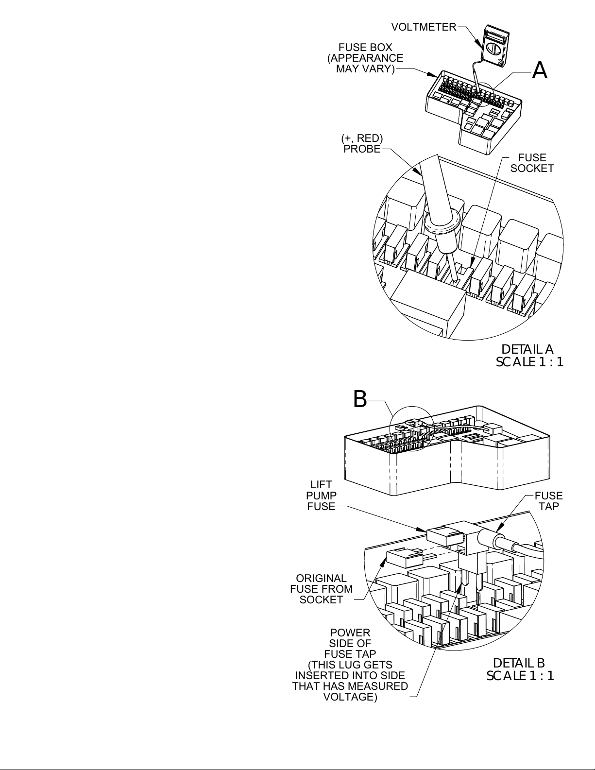
Topic: Finding proper Fuse Position, Socket Power Side
and Fuse Tap Orientation
This kit uses a Fuse Tap Assembly in the wiring harness, to
allow a power tap from the Under-Hood Fuse Box to power the
Lift Pump / Filtration System. Possible Fuse Positions (see lid of
Fuse Box) for this application include Fuse Numbers (choose
one):
9 or 10.
A Test Light or Voltmeter is required to determine the proper
orientation of the Fuse Tap. Use the (Positive - Red) probe of
the Test Light or Voltmeter to determine the "Power Side" of the
Fuse Socket. For the proper leg of the Fuse Tap to be
referenced, place probe into one side of the Fuse Socket, while
the other Probe (Negative – Black) is placed firmly against a
good grounded metal surface. If the probe size is too large, a
small straitened paperclip can be used to help establish
readings. Check the following conditions before installing the
Fuse Tap:
• Check Door or Lid Label for Fuse Block, to verify the
correct location of the Fuse (see list above).
• Remove Original Fuse from the Socket, using Fuse
Pulling Tool or Needle Nose Pliers.
• With Ignition Key in the "OFF" position, does either
side of the Fuse Socket have voltage? If voltage is
measured, then look for alternate location, as
voltage indicates the wrong operating behavior and
therefore is a wrong Fuse Position.
• With Ignition Key in the "ON" position,
does either side of the socket have
voltage? If no voltage is detected, then
re-inspect test equipment and proper
Fuse Position. If voltage is measured,
then note which side (of the two
positions) had measured voltage. This
side will be considered to be the "Socket
Power Side". When inserting the Fuse
Tap, note that the "Power Side" of the
Fuse Tap must be inserted into the
Socket Power Side to have the proper
Fuse Tap Orientation. SPECIAL NOTE:
Ignition Key may have to be cycled
(OFF-ON-OFF) while observing the
Voltmeter or Test Light, as power may
be intermittent (depending on the actual
circuit being tested).
• Note the Fuse and position of the fuses
within the Fuse Tap (bottom fuse is the
original fuse removed from the socket,
while the "upper" fuse is the fuse for the
Lift Pump).
Table des matières


