Fresh Breeze SNAP Manuel utilisateur

SNAP
MANUAL
ASSEMBLY OPERATION MAINTENANCE

INTRODUCTION 03
ASSEMBLING THE MOTOR 04
TECHNICAL SPECIFICATIONS 08
FUEL AND OIL 09
STARTING THE MOTOR 10
SETTING THE CARBURETTOR 11
MANUAL STARTER 12
PROPELLER 14
CIRCUIT DIAGRAM 16
GAS HANDLE RESPECT 17
GAS HANDLE AIRBOSS 18
HARNESS AND SUSPENSION 19
PREFLIGHT CHECK 22
INSPECTION CYCLES 23
TABLE OF CONTENTS
02
SNAP
MANUAL

This manual has been compiled to provide pilots
and instructors with information contributing to the
safe and efficient operation of this paratrike. Apart
from important statutory information, this manual
also contains additional information provided by the
motor paraglider manufacturer.
To fly this air vehicle, you need to have the pilot’s
licence for motor paragliders. In addition, it is only
permitted to start and land at approved landing
places. Flights outside the uncontrolled flight space
require a permit, which is mostly requested and
granted via radio.
Further legal requirements such as taking out third
party liability insurance have to be observed. The
pilot has to acquaint himself with the particular
properties and peculiarities of the motor paraglider
prior to starting a flight.
It is compulsory to read the manuals and operating
instructions and to become acquainted with motor,
equipment and all other particulars. It is not permitted
to perform air acrobatics with this motor paraglider.
The legal basis for the operation of ultralight para-
gliders is governed by air traffic laws. Particulars
may be gathered from the associated ordinances.
The provisions and requirements contained therein
have to be observed during operation. The Snap has
been designed, constructed, tested and approved
in accordance with the airworthiness requirements
for motor paragliders. The DULV (German Ultralight
Flight Association) is responsible in this respect.
PRECAUTIONS
Read the flight safety messages in the different
publications, for instance:
Aviation journals
Aviator pocket diaries
News for aeronauts (NfLf)
Federal Aviation Office (LBA) and Federal
Office for Flight Safety (BFS) communications, etc.
Do not carry out any flights during turbulent weather
conditions as a paraglider in principle only obtains
its shape because of its internal pressure. This
internal pressure can only be maintained during
normal oncoming flow conditions.
Exercise particular caution in case there is a
thunderstorm tendency. At any rate, avoid to fly too
close to the storm front to prevent being sucked
into the cloud. In case of emergency, carry out an
off-field landing. Obtain information about low level
flight zones of military aircraft and avoid these.
INTRODUCTION
03
SNAP
MANUAL

First of all, the pedestal should be pushed into the backframe
and …
… secured by means of the 3 clips. The motor can now stand
on its own.
Now assemble respectively the left and right cage quarters
and …
… fasten them on the backframe.
ASSEMBLING THE MOTOR
04
SNAP
MANUAL

The cage is anchored in the black clips by means of the
internal pins.
Fixation with the 4 Velcro®strips prevents the cage from
unintentionally detaching from the frame.
The cage parts themselves are held together with the attached
Velcro®strips.
The bottom Velcro®strip is passed through the guard rail and
fastened.
ASSEMBLING THE MOTOR
04
SNAP
MANUAL

The starter handle is hooked into the steel loop that is located
on the top right part of the cage.
For the backframe pedestal to be detachable, the shoulder
straps are equipped with push-in buckles. These have to be
pushed together again during assembly.
ASSEMBLING THE MOTOR
06
SNAP
MANUAL
The back pad is also held by means of a Velcro®fastener that
is folded over the top and bottom frame bracing.
Velcro®fasteners are also used to fasten the back pad
laterally on the frame.

This special back pad prevents the motor from twisting too
badly on the pilot’s back due to the high torsional force
generated by the motor.
The photo on the right shows the vehicle tool kit provided that
can be used to perform the most important operations on the
motor.
Content:
· Allen wrench 4/5/6 mm
· Combination wrench 8/10 mm
· Plug spanner with screw driver
ASSEMBLING THE MOTOR
07
SNAP
MANUAL

TECHNICAL SPECIFICATIONS
08
THE FOLLOWING VALUES DEPEND ON:
WEATHER, CLIMATE, POSITION, PILOT WEIGHT, TYPE AND SIZE OF CANOPY AS WELL AS FLYING ALTITUDE .
EFFECTS OF GAS LEVER POSITION, FLYING ALTITUDE,
TYPE AND SIZE OF CANOPY AND PILOT WEIGHT ON CONSUMPTION.
SNAP
MANUAL
Motor Snap Cisco
Type two-stroke, 1 cylinder
Cooling fan cooling
Starter manual
Carburettor Walbro
Exhaust Resonator
Propeller 2-blade
Diameter 120 cm
Weight 21 Kg
Tank capacity 8 litres
Max. start weight 130 kg
Consumption approx. 3 litres/hour
Flight duration up to 2.5 hours
Rpm 8700 rpm
Propulsive force up to 50 kg
Climbing rate up to 2 m/sec
Gas lever low output low consumption
Gas lever high output high consumption
Low flying altitude low consumption
High flying altitude high consumption
Small canopy high consumption high speed
Large canopy low consumption low speed
Light pilot low consumption low speed
Heavy pilot high consumption high speed

The motor is supplied with 2 tank lids. The one with the vent
hole is intended to be used for flying, while the closed lid is
to be used for transport. Prior to a flight it has to be ensured
that the vent lid has been screwed on, or else the motor will
go out after a short flying time. This is because a vacuum is
generated and the fuel flow is stopped.
From the tank, the fuel is channelled to the petrol filter via the
angled outlet (to be checked before every flight).
FUEL AND OIL
09
SNAP
MANUAL
After that, the fuel is taken through the ball pump and to the
…
… fuel tap and finally to the carburettor.
The engine runs with a fuel-oil mix of 1:50
(2 % Castrol RS2T with 95 octan gas).
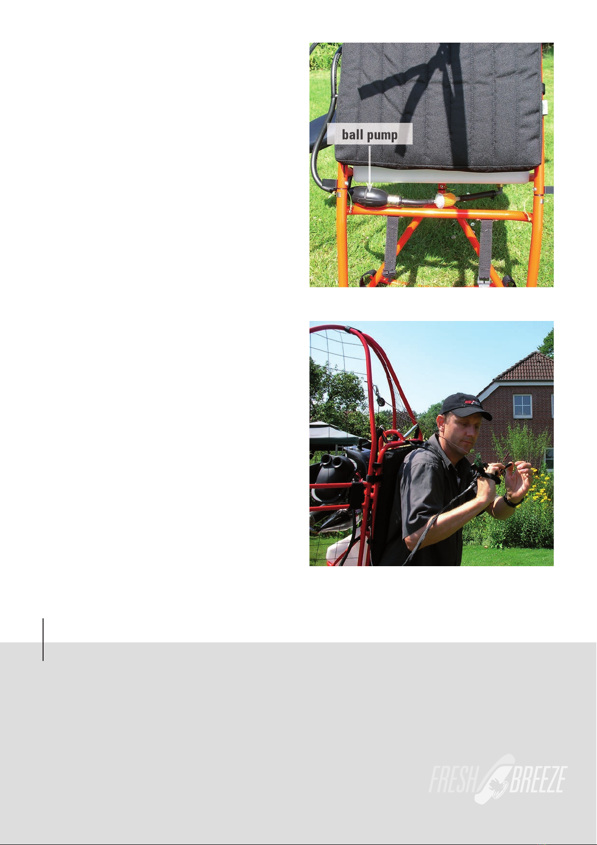
The diaphragm carburettor has no special choke system.
However, a cold motor requires more fuel. To facilitate the
starting process, press the ball pump with one hand for
approx. 1 second. This causes the fuel to be channelled to
the carburettor. The ball pump is located underneath the
tank. At the same time, you need to press the pin (No. 3 on the
carburettor illustration on page 10) on the carburettor.
STARTING THE MOTOR
10
SNAP
MANUAL
Now you should take the motor on your back and reach for
the starter handle on the top right. While doing so, hold the
gas handle in your hand. The motor can now be started with
a firm pull.
As a rule, the motor is started with gas. If the motor does not
start, the process with the ball pump should be repeated. If
the motor has been flooded, it must be started at full throttle.
Caution. The motor may never be started on the ground! There
is a high risk of injury!
ball pump
Table des matières
Autres manuels Fresh Breeze Paramoteur


Manuels Paramoteur populaires d'autres marques

Sky Country
Sky Country RESCUE SC-25 Manuel utilisateur

FLY
FLY TRIKE-FLASH Manuel utilisateur

Parajet
Parajet Volution Micro Manuel utilisateur

Cruise Carbon
Cruise Carbon INSTINCT Guide rapide

Fly Products
Fly Products FLASH 100 Manuel utilisateur

Opale-Paramodels
Opale-Paramodels Backpack XXS3 Manuel utilisateur


