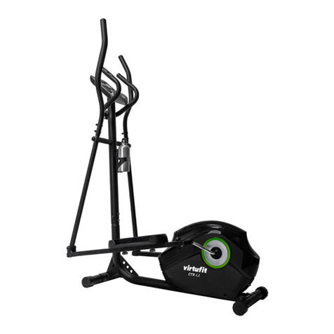
Freespirit C249 30816 2 Manuel utilisateur

ELLIPTICAL
OWNER`S
MANUAL
Model No.
C249 30816 2
FREE SPIRIT
ELLIPTICAL
SERVICE
Is at
YOUR
SERVICE
•Assembly
•Operation
•Exercise
•Parts
•Warranty
CAUTION
You must read and
understand this
owner’s manual
before operating
unit.

©2009
1
Manufacture’s One-Year Limited Warranty
Your Free Spirit Elliptical is warranted for one year from the date of purchase against defects in material when
used for the purpose intended, under normal conditions and provided it receives proper care. Any part found
defective or missing will be sent at no cost when returned in accordance with the terms of this warranty.
This warranty is not transferable and is extended only to the original owner.
The warranty shall not apply to exercise units which are (1) used for commercial or other income producing
purposes, or (2) subject to misuse, neglect, accident or unauthorized repair and alterations.
This warranty provided herein is lieu of all other express warranties, any implied warranties, including any
implied warranties of merchantability of fitness for particular purpose, are limited in duration to the first 12
months from date of purchase. All other obligations or liabilities, including liability for consequential damages
are hereby excluded.
Repair Parts and Service
All of the parts for the unit shown can be ordered from: Maurice Pincoffs Canada Inc. 6050 DON MURIE
STREET, NIAGARA FALLS, ONTARIO L2E 6X8. When ordering parts, the parts will be sent and billed at the
current prices. Prices may be subject to change without notice. Check or money order must accompany all
orders. Standard hardware items are available at your local hardware store.
To ensure prompt and correct handling of any errors, or to answer any questions, please call our
Toll Free number, 1-888-707-1880, or local number 1-905-353-8955 or fax 1-905-353-8968 or
Monday to Friday Eastern Standard time.
Always include the following information when ordering parts
zModel number
zName of each part
zPart number of each part
TABLE OF CONTENTS
WARRANTY..………………………….…….…....1
SAFETY PRECAUTIONS………………..…..…..2
HARDWARE LIST………………………………..3
ASSEMBLY INSTRUCTION......………………...5
MOVING YOUR ELLIPTICAL………………....10
LUBRICATION………………….………………..10
COMPUTER OPERATION………………….…..11
PARTS LIST & DIAGRAM..………………...…..14
TRAINING GUIDELINES…..…………..….…....19
ORDERING REPLACEMENT PARTS……...….24
SERVICE AND PARTS…………………….…..…25

©2009
2
SAFETY PRECAUTIONS
Thank you for purchasing our product. Even though we go to great efforts to ensure the quality of each
product we produce, occasional errors and /or omissions do occur. In any event should you find this product
to have either a defective or a missing part please contact the manufacturer at 1-888-707-1880 for a
replacement.
This product has been designed for home use only. Product liability and guarantee conditions will not be
applicable to products being subjected to professional use or products being used in a gym center.
This exercise equipment was designed and built for optimum safety. However, certain precautions apply
whenever you operate a piece of exercise equipment. Be sure to read the entire manual before assembly and
operation of this machine. Also, please note the following safety precautions:
1. Read the OWNER’S OPERATING MANUAL and all accompanying literature and follow it carefully before
using your elliptical.
2. If dizziness, nausea, chest pains, or any other abnormal symptoms are experienced while using this
equipment, STOP the workout at once. CONSULT A PHYSICIAN IMMEDIATELY.
3. Inspect your exercise equipment prior to exercising to ensure that all nuts and bolts are fully tightened before
each use.
4. The elliptical must be regularly checked for signs of wear and damage. Any part found defective must be
replaced with a new part from the manufacturer.
5. Fitness equipment must always be installed on a flat surface, do not place the unit on a loose rug or uneven
surface. It is recommended to use an equipment mat to prevent the unit from moving while it is being used,
which could possibly scratch or damage the surface of your floor.
6. No changes must be made which might compromise the safety of the equipment.
7. It is recommended to have a minimum of 2’ safe clearance around the exercise equipment while in use.
8. Keep children and pets away from this equipment at all times while exercising.
9. Warm up 5 to 10 minutes before each workout and cool down 5 to 10 minutes afterward. This allows your
heart rate to gradually increase and decrease and will help prevent you from straining muscles.
10.Never hold your breath while exercising. Breathing should remain at a normal rate in conjunction with the
level of exercise being performed
11.Always wear suitable clothing and footwear while exercising. Do not wear loose fitting clothing that could
become entangled with the moving parts of your elliptical.
12.Care must be taken when lifting or moving the equipment, so as not to injure your back. Always use
proper lifting techniques.
13.User weight should not exceed 325 lbs.
WARNING: BEFORE BEGINNING ANY EXERCISE PROGRAM CONSULT YOUR PHYSICIAN. THIS
IS ESPECIALLY IMPORTANT FOR INDIVIDUALS OVER THE AGE OF 35 OR PERSONS
WITH PRE-EXISTING HEALTH PROBLEMS. READ ALL INSTRUCTIONS BEFORE
USING ANY FITNESS EQUIPMENT. WE ASSUME NO RESPONSIBILITY FOR
PERSONAL INJURY OR PROPERTY DAMAGE SUSTAINS BY OR THROUGH THE USE
OF THIS PRODUCT.

©2009
3
HARDWARE LIST
70. 5/16" x 15m/m
Hex Head Bolts (8pcs)
#97. 5/16"x 23 x1.5T
Flat Washer (6pcs) #102. 5/16"x 23 x2T
Curved Washer (2pcs)
#78. M5 x 10m/m
Phillips Head Screw (4pcs)
#101. 17m/m
Wavy Washer (2pcs)
#75. 5/16" x 15m/m
Button Head Socket Bolts (6pcs)
#71. 5/16 x 32m/m
Hex Head Bolts (2 pcs)
#98. 5/16" x 20 x 1.5T
Flat Washe
r
(
4
p
cs
)
#105. 5/16" x 7T
Nyloc Nut (2 pcs) #89. 3/8" x 7T
Nyloc Nut (2 pcs)
#94. 3/8" x 19 x 1.5T
Flat Washer (2 pcs)
#76. 5/16 x 3/4"
Button Head Socket Bolts (2 pcs)
#77. 3/8 x 2-1/4"
Button Head Socket Bolts (2 pcs)

©2009
4
#84. 3.5x12m/m
Self Tapping Screw (8pcs) #79. M5 x 15m/m
Phillips Head Screw (8pcs)
#108. Combination M5 Allen Wrench
& Phillips Head Screw Driver (1 pc)
#110. 12m/m Wrench ( 1pc) #111. 13/14m/m Wrench ( 2pcs)

©2009
5
ASSEMBLY INSTRUCTION
This manual is designed to help you easily assemble, adjust and use this machine. Please read this manual
carefully. For the sake of familiarizing yourself with the parts identified in the instruction, first study the overview
drawing.
Set all parts in a clear area on the floor and remove the packing material. Refer to the parts list for help to identify
the parts.
It will take two people to assemble your unit.
Ensure all bolts are firmly tightened after each step.
STEP 1: CONSOLE MAST ASSEMBLY
1. Locate the Console Mast (10) and Console Mast Cover (41) and slide the Cover onto the Mast as far as it will
go. Make sure the Console Mast Cover (41) is facing the correct way.
2. At the top opening of the Main Frame (1) of the elliptical is a Computer Cable (32). Unravel and straighten out
the Computer Cable (32) and feed it into the bottom of the console mast tube (10) and out of the top opening.
3. Install the Console Mast (10) into the receiving bracket in the top of the Main Frame (1).
Put the 4pcs of 5/16"x 23 x1.5T Flat Washers (97) onto the 4pcs of 5/16" x 15m/m Hex Head Bolts (70) and
the 2pcs of 5/16” x 23 x 2T Curved Washers (102) onto the 2pcs of 5/16" x 15m/m Hex Head Bolts (70). Install
and hand tighten by using the 12m/m Wrench (110).
NOTE: There is a electrical wire running through the Console Mast Tube (10). Be careful not to damage or
pinch this Computer Cable (32) during this procedure.
4. Locate the Console (31) and the 4 pcs of M5 x 10m/m Phillips Head Screws (78) by using the Combination
M5 Allen Wrench & Phillips Head Screw Driver (108).
5. There will be three electrical wire connectors at the top opening of the Console Mast (10), two 2 pin Hand
pulse Cables (37-3), one Computer Cable (32). Connect these to the mating connectors on the back of the
Console (31). The connectors are keyed so you cannot plug them in the wrong way so do not force them. The 2
pin Hand pulse Cables are both the same. It does not matter how you connect them.
6. Store the excess wire back into the Console Mast (10), carefully install the Console (31) onto the mounting
plate of Console Mast (10) and secure using the 4 pcs of M5 x 10m/m Phillips Head Screws (78).

©2009
6

©2009
7
STEP 2: HANDLE BAR ASSEMBLY
1. Install the 2 pcs of 17m/m Wave Washers (101) onto the Left and Right side of the Handle Bar axle.
2. Slide the Lower Left and Right Handle Bars (4&5) onto the appropriate side of the axle.
3. Put the 2 pcs of 5/16" x 23 x 1.5T Flat Washers (97) onto the 2 pcs of 5/16" x 15m/m Hex Head Bolts (70) and
install, and tighten, in the threaded holes in the ends of the axle.
4. Install the Left and Right Handle Bars (13&14) into the Lower Left and Right Handle Bars (4&5) with 6pcs of
5/16 x15m/m Button Head Socket Bolts (75) by using the Combination M5 Allen Wrench & Phillips Head
Screw Driver (108).

©2009
8
STEP 3: CONNECTING ARM ASSEMBLY
1. Align the hole in the end of the Connecting arms (L&R)(7&8)(pivoting rod end) with the hole in the bracket of
the Lower Handle Bars (L&R)(3&4). The rod end should be on the inside of the Lower Handle Bars
(L&R)(3&4) bracket. Take 2pcs of 5/16" x 1-1/4" Hex Head Bolts (71) and install it through the Lower Handle
Bars (L&R)(3&4) bracket and the rod end. Install 2pcs of 5/16" x 20 x 1.5T Flat Washers (98), 2pcs of 5/16" x
7T
Nyloc Nuts (105) tighten firmly using the 12m/m Wrench (111) on the 5/16" x 7T Nyloc Nut (105) and one on
the 5/16" x 1-1/4" Hex Head Screw (71).
2. Install the 2 pcs of Rails (15) into the receiving bracket in the end of Main Frame (1) with 2 pcs of 3/8” x 2-1/4”
Button Head Socket Bolts (77), 2pcs of 3/8" x 19 x 1.5T Flat Washers (94) and 2 pcs of 3/8" x 7T Nyloc Nut
(89) by using 2 pcs of the 13/14m/m Wrench (111).
3. Put the Lug Covers (L&R) (61& 62) onto the Rail Strap (16). Slip the Rail Strap (16) through the slots in the
Lug Covers (L&R) (61& 62), then Install onto the Rails (15) with 2 pcs of 5/16” x 3/4” Button Head Socket
Bolts (76) and 2 pcs of 5/16" x 20 x 1.5T Flat Washers (98) by using Combination M5 Allen Wrench & Phillips
Head Screw Driver (108).

©2009
9
STEP 4: PLASTICS ASSEMBLY
1. Install the Connecting Arm Covers (L & R) (59 & 60) over the connection of the rod end and Lower Handle
Bars (4 & 5) with 4pcs of M5 x 15m/m Phillips Head Screws (79) and 2pcs of ψ3.5x12m/m Self Tapping
Screws (84) by using the Combination M5 Allen Wrench & Phillips Head Screw Driver (108).
2. Install the 2pcs of Wheel Covers (52) using the 4pcs of M5x15m/m Phillips Head Screws (79).
3. Install the Front Handle Bar Cover (L & R) (54 & 56) and Rear Handle Bar Cover
(L & R) (55 & 57) over the Handle Bars (13&14) axle connections with the 6 pcs of 3.5x12m/m Self
Tapping Screws (84) by using Phillips Head Screw Driver (108).
PLEASE ENSURE ALL FASTENERS ARE TIGHT AFTER THE COMPONENTS HAVE BEEN
ASSEMBLED
Table des matières
Autres manuels Freespirit vélo elliptique


Manuels vélo elliptique populaires d'autres marques

Weslo
Weslo Momentum 4.0 Elliptical Manuel d'utilisation et d'entretien

Progear Fitness
Progear Fitness Air elliptical pro 1307 Manuel utilisateur

Torque Fitness
Torque Fitness XPLLP Manuel utilisateur

Octane Fitness
Octane Fitness PRO3700C Manuel utilisateur

Xterra
Xterra FS5.8e Manuel utilisateur

Bodyguard
Bodyguard E-40 Manuel utilisateur

Bonn Germany
Bonn Germany Concept 2.2 Manuel utilisateur

Precor
Precor Resolute RSL 620 Manuel utilisateur

NordicTrack
NordicTrack E 9.2 Elliptical Manuel utilisateur

Vision Fitness
Vision Fitness X6600iNetTV Manuel utilisateur

Matrix
Matrix MX-A5x Manuel utilisateur

SportsArt Fitness
SportsArt Fitness ECO-NATURAL Elite E874 Manuel utilisateur