Fortune Z-Wave Plus v2 Manuel utilisateur

AYRMODZW34MNL0050
ISL000000000
Smart Module Installation
ZWave Plus™v2 Assure Lock®2
Models: YRD410, YRD420, YRD430, YRD450, YRD420F, YRD450F
If your lock is already installed,
remove the batteries.
Insert the Yale ZWave Plus™ v2
Smart Module into the battery
compartment slot.
Reinsert the batteries.
Open the Yale Access App and
navigate to your lock model.
3a. Select ‘Lock Settings’.
3b. Select ‘Yale Smart Module’.
3c. Follow steps in the app
to complete set-up.
To remove the Yale ZWave Plus™ v2
smart module from your system,
select the disconnect ZWave™
option from lock settings
in the Yale Access App.
1 2 3 4
NOTE: Anytime you add or remove a Smart Module from your lock, the batteries must be removed.
Anytime you add or remove a
Smart Module from your lock,
the batteries must be removed
Smart Module Installation
ZWave Plus™v2 Assure Lock®
Models: YRD216, YRD226, YRD256, YRL226, YRL216
If your lock is already installed,
remove the batteries.
Insert the Yale ZWave Plus™ v2
Smart Module into the battery
compartment slot.
Reinsert the batteries.
If you have SmartStart enabled
with your ZWave™ system,
follow in-app prompts to add a
new device. If you do not have
SmartStart or are not sure,
follow the steps below.
3a. Enter your locks master entry
code, followed by the
3b. Press the 7key followed by
the
3c. Press the 1key followed by
the
To remove the ZWave Plus™ v2
Smart Module from your system,
open the smart home
or alarm app and follow the
instructions for removing a device.
4a. Enter your locks master entry
code, followed by the
4b. Press the 7key followed by the
4c. Press the 1key followed by the
1 2 3 4
Anytime you add or remove a
Smart Module from your lock,
the batteries must be removed
If prompted,
scan QR code
This device is a security enabled ZWave Plus™
v2 product that is able to use encrypted ZWave
Plus™ v2 messages to communicate to other
security enabled ZWave Plus™ v2 products.
This device must be used in conjunction with
a Security Enabled ZWave™ Controller in order
to fully utilize all implemented functions.
This product can be operated in any ZWave™
network with other ZWave™ certified devices
from other manufacturers. All non-battery
operated nodes within the network will act
as repeaters regardless of vendor to increase
reliability of the network.
Changes or modifications to this device,
not expressly approved by
MASTER LOCK Group
could void the user’s authority
to operate the equipment.
FCC:
Class B Equipment
This equipment has been tested and found to comply with the limits
for a Class B digital device, pursuant to Part 15 of the FCC Rules.
These limits are designed to provide reasonable protection against
harmful interference in a residential installation. This equipment
generates, uses, and can radiate radio frequency energy and, if
not installed and used in accordance with the instructions, may
cause harmful interference to radio communications. However,
there is no guarantee that interference will not occur in a particular
installation. If this equipment does cause harmful Interference to
radio or television reception, which can be determined by turning
the equipment off and on, the user is encouraged to try to correct the
interference by one or more of the following measures:
• Reorient or relocate the receiving antenna.
• Increase the separation between the equipment and receiver.
• Connect the equipment into an outlet on a circuit different from
that to which the receiver is connected.
• Consult the dealer or an experienced radio/TV technician for help.
THIS DEVICE COMPLIES WITH PART 15 OF THE FCC RULES.
OPERATION IS SUBJECT TO THE FOLLOWING TWO CONDITIONS.
(1) THIS DEVICE MAY NOT CAUSE HARMFUL INTERFERENCE,
AND (2) THIS DEVICE MUST ACCEPT ANY INTERFERENCE
RECEIVED, INCLUDING INTERFERENCE THAT MAY CAUSE
UNDESIRED OPERATION.
This equipment complies with the FCC radiation limits set forth for
an uncontrolled environment. This equipment should be installed
and operated with minimum distance 20cm between the radiator
& your body.
Industry Canada:
Section 7.1.2 of RSSGEN Under Industry Canada regulations,
this radio transmitter may only operate using an antenna of a type
and maximum (or lesser) gain approved for the transmitter by
Industry Canada. To reduce potential radio interference to other
users, the antenna type and its gain should be so chosen that the
equivalent isotropically radiated power (e.i.r.p.) is not more than t
hat necessary for successful communication.
En vertu des règlements d’Industrie Canada, cet émetteur radio
ne peut fonctionner avec une antenne d’un type et un maximum
(ou moins) approuvés pour gagner de l’émetteur par Industrie
Canada. Pour réduire le risque d’interférence aux autres utilisateurs,
le type d’antenne et son gain doivent être choisies de façon que la
puissance isotrope rayonnée équivalente (PIRE) ne dépasse pas ce
qui est nécessaire pour une communication réussie.
Section 7.1.3 of RSSGEN This Device complies with Industry Canada
License-exempt RSS standard(s). Operation is subject to the
following two conditions: 1) this device may not cause interference,
and 2) this device must accept any interference, including
interference that may cause undesired operation of the device.
Cet appareil est conforme avec Industrie Canada RSS standard
exemptes de licence(s). Son fonctionnement est soumis aux
deux conditions suivantes: 1) ce dispositif ne peut causer des
interférences, et 2) cet appareil doit accepter toute interférence,
y compris les interférences qui peuvent causer un mauvais
fonctionnement du dispositif.
CAN ICES3B/NMB3B
24/7 18552135841 Yale Home ShopYaleHome.com
Yale® is a registered trademarks of Master Lock Company LLC and its affiliates. Other products’ brand names may be trademarks or registered trademarks of their respective owners
and are mentioned for reference purposes only. © Copyright 2023. All rights reserved. Reproduction in whole or part without the express written permission of Master Lock Company LLC
and its affiliates is prohibited.
P/N YRD604-KD-BLE-0047 Rev A
Yale Pro2
Keyed YRD614 / YRD624
Download Yale Access App
Create an account if you don’t already have
one, and tap “Set Up a Device”.
Note: If you have an account with the August App, use the same username and
password for the Yale Access App.
Install Your Lock
Follow the step-by-step Installation Guide in this manual (pages 923),
or refer to the app for installation instructions with helpful videos.
Note: If you use the app, please tear off the Door Checker and the Marking
Template (pages 58) to use when prompted.
Set Up and Use Your Lock
Create permanent entry codes, issue entry codes for guests, operate
your lock with your phone and more (pages 2435).
Trusted Every Day ISL222500003

P/N YRD604-KD-BLE-0047 Rev A

P/N YRD604-KD-BLE-0047 Rev A
Contents
In the Box 4
Door Checker 5
Marking Templates 7
Installation Guide 9
Remove Existing Deadbolt 10
Check Door Measurements 11
Make or Adjust Holes 12
Install Deadbolt Latch 13
Install Exterior Keypad 14
Install Mounting Plate 15
Attach Wire Cable to Interior Lock 16
Install Interior Lock 17
Test Thumbturn and Key 18
Install Yale Smart Module (Optional) 19
Install DoorSense (Optional) 20
Install Batteries and Replace Cover 23
Using Your Lock 24
Connecting to Your Lock 25
Creating and Managing Entry Codes 26
Set Up HomeKit (Optional) 27
LED Alerts 28
Resetting Your Lock to Factory Defaults 29
Features 30
App Settings 31
Lock Operations Troubleshooting 33
Hardware Troubleshooting 35

4
P/N YRD604-KD-BLE-0047 Rev A
In the Box
Lock Hardware
b.
c.
d.
e.
X 4
X 4
X 2
X 2
X 2
X 2
X 2
Add-Ons
123
5 76
4
UP
1. Exterior Keypad
2. Interior Lock
3. Strike Plate
4. Adjustable Deadbolt & Key
5. Manual
6. Reset Pin
7. Mounting Plate
8. AA Batteries
9. Screws
a. Strike Plate and Deadbolt Screws
b. Teal Screw Set B
c. Black Screw Set C
d. Silver Screw Set D
e. Optional Security Strike Plate Screws
10. DoorSense
a. Housing
b. Cover
c. Mounting Tape
d. Screws
e. Flush Mount Cap
11. Smart Module
(Included with select models)
8
10 9
11
a. a.d.
e.b.
c.
AA

5
P/N YRD604-KD-BLE-0047 Rev A
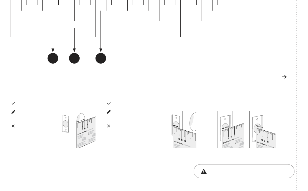
Tear Along the Dotted Line
Door Checker Part 1
Measure Clearance Measure Door Thickness Measure Backset
A. 2” minimum clearance between top
of the door knob and center of deadbolt
hole.
B. 13/8” door thickness; use teal
(shortest) screws.
C. 13/8” - 13/4” door thickness;
use black (medium) screws.
D. 13/4” - 21/4” door thickness;
use silver (longest) screws.
E. 23/8” backset, use out of box latch
setting.
F. 23/4” backset, adjust latch setting
(Step 2, point 1 of this manual).
Greater than A B, C or D Equals E or F
Less than A Less than B or
greater than D
Doesn’t equal E or F
(Your door is not a match)
(Your door is not a match)
(Your door is not a match)
10 2 3 4 5
6
Door Checker Part 1
v
B A D
C E
v
v
See Reverse for Part 2
1/8 1/8 1/8 1/8 1/83/8 3/8 3/8 3/8 3/85/8 5/8 5/8 5/8 5/87/8 7/8 7/8 7/8 7/8
1/4 1/4 1/4 1/4 1/4
1/2
10 2 3 4 5
1/2 1/2 1/2 1/2
3/4 3/4 3/4 3/4 3/4
B A E
DC F
6
P/N YRD604-KD-BLE-0047 Rev A
Tear Along the Dotted Line
Door Checker Part 2 See Reverse for Part 1
Measure Face Bore
Equals G or H
Less than G Less than I
G. 11/2” face bore diameter.
H. 21/8” face bore diameter.
Measure Edge Bore and Strike Pocket
I. 1” edge bore diameter;
1” strike pocket diameter and depth.
Equals I
Greater than IGreater than H
(Adjust diameter to G or H) (Adjust diameter to I)
(Your door is not a match)(Your door is not a match)
(Edge Bore)Door (Strike Pocket)
Frame
Diameter Depth
Minimum strike pocket depth is 1”.
HI G
1/8 1/8 1/8 1/8 1/83/8 3/8 3/8 3/8 3/85/8 5/8 5/8 5/8 5/87/8 7/8 7/8 7/8 7/8
1/4 1/4 1/4 1/4 1/4
1/2
10 2 3 4 5
1/2 1/2 1/2 1/2
3/4 3/4 3/4 3/4 3/4

7
P/N YRD604-KD-BLE-0047 Rev A
Tear Along the Dotted Line
Marking Template for 21/8” (54mm) Face Bore
Center of
1” (25mm)
Edge Bore
Center of
1” (25mm)
Edge Bore
Centerline
Center of
21/8” (54mm)
Face Bore
Center of
21/8” (54mm)
Face Bore
I H
13/8” (35mm)
Door Thickness
B23/8” (60mm)
Backset
E
13/4” (44.5mm)
Door Thickness
C23/4” (70mm)
Backset
F
21/8”

8
P/N YRD604-KD-BLE-0047 Rev A
Marking Template for 11/2” (38mm) Face Bore
Center of
1” (25mm)
Edge Bore
Center of
1” (25mm)
Edge Bore
Centerline
Center of
11/2” (38mm)
Face Bore
Center of
11/2” (38mm)
Face Bore
11/2”
I G
13/8” (35mm)
Door Thickness
B23/8” (60mm)
Backset
E
13/4” (44.5mm)
Door Thickness
C23/4” (70mm)
Backset
F
Tear Along the Dotted Line
Ce manuel convient aux modèles suivants
7
Table des matières
Autres manuels Fortune Verrouillage


