Forney IDD Series Manuel utilisateur

www.forneycorp.com
BURNERS IGNITERS DAMPERS CONTROLS
B

372001-24 Rev. B
i
NOTICE: Read this manual in its entirety before commencing work of any kind. Only
experienced personnel familiar with this type of equipment, should install, setup, and
service this equipment.
NOTICE: The equipment serial number should be referenced any time that contact
is made with Forney. The serial number can be found on the Forney Data Label/Plate
(mounted on the equipment).
NOTICE: If any of the procedures or instructions provided in this manual are unclear,
contact Forney for resolution. Forney Corporation offers complete, on-site service solutions
to ensure proper installation, programming, commissioning, and troubleshooting.
WARNING: Never use this equipment in any manner for which it was not designed.
Improper use can severely impact user safety. The Forney Corporation cannot be held
liable for any damages resulting from such use! Failure to heed this warning COULD result
in death or serious injury.
TECHNICAL RELEASE LOG
REV MODIFICATION DATE
A Original Release 04/2021
B General Improvement 09/2022

372001-02 Rev Kv
TABLE
OF
CONTENTS

0.1 Introduction
0.2 Proprietary Notice
0.3 Safety Awareness
0.4 Personal Protective Equipment (PPE)
0.5 Typical Safety Alert Symbols and Action Icons
0.6 Additional Documentation
1.1 Summary
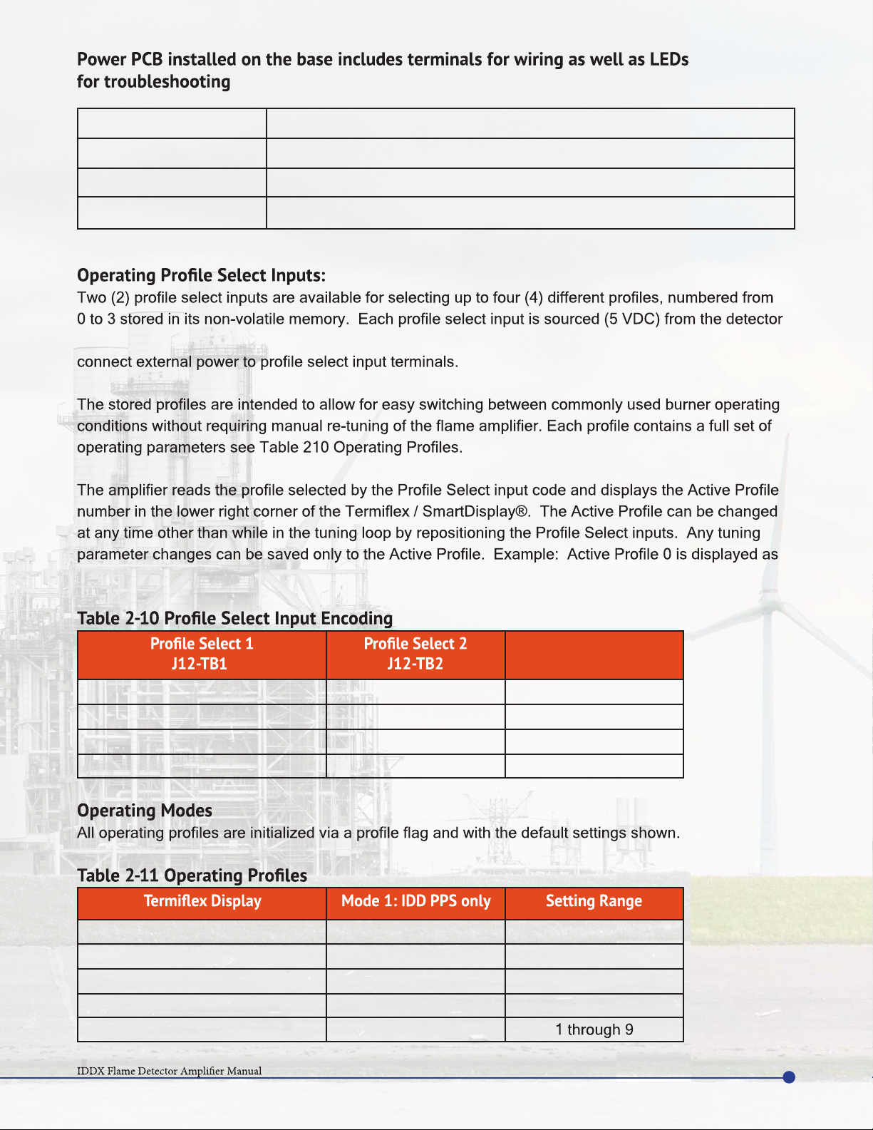
Operating Modes
1.2 Dimensions
1.3 Technical Data
1.4 Codes, Standards, and Agency Approvals
2.1 Location
2.2 Required Site-Service Connections
2.3 Wiring
Mode
IDD Channel Tuning
Flame Failure Response Time Delay for Modes 1
Self-Check Cycle Time for Modes 1
Functions Unavailable While Tuning
Analog Outputs
4.1 Service
Coordination
Handling
Storage
4.2 Troubleshooting
5.1 RMA / Warranty
5.2 Parts and Accessories
6.1 Common Acronyms
6.2 Common Regulatory Agencies
TABLE OF CONTENTS
ii
iii
iii
iii
iv
iv
iv
1
1-2
3-5
6
7
8
9
9
9
10
10
12
13
13-19
20
21
22
23
23
23
24
24
24
24
24
25-26
27
27
27-28
29
29
30
372001-24 Rev. B

iii
INTRODUCTION
0.1
PROPRIETARY NOTICE
0.2
SAFETY AWARENESS
0.3
This manual serves as a guideline to service technicians for the basic installation, setup, and troubleshooting
All personnel should become thoroughly familiar with the contents of this manual prior to installing,
setting-up and servicing this equipment. Because it is virtually impossible to cover every situation that
might occur during operation and maintenance of the equipment described in this publication, personnel
mentioned herein.
The contents of this publication are proprietary data of Forney Corporation. Reproduction or use of any
part of the publication for purposes other than the support of the equipment for which it is published is
permissible only if expressly authorized in writing by Forney.
Safety is YOUR responsibility and must always be primary concern. The guidelines covered in this
manual will greatly improve your ability to safely install and maintain this equipment. It is the equipment
owner’s responsibility to ensure that the concerned personnel fully understand and abide by all site-
common sense!
372001-24 Rev. B

PERSONAL PROTECTIVE
EQUIPMENT (PPE)
0.4
v
iv
372001-24 Rev. B
TYPICAL SAFETY ALERT
SYMBOLS AND ACTION ICONS
0.5
ADDITIONAL DOCUMENTATION
0.6
ALL labels in this manual should be carefully observed, read, and understood. Standard labels are as
IDD Detector Manual
DANGER Indicates a hazardous situation which, if not avoided, will result in
death or serious injury.
WARNING Indicates a hazardous situation which, if not avoided, could result in
death or serious injury.
CAUTION Indicates a hazardous situation which, if not avoided, could result in
minor or moderate injury.
NOTICE Provided to notify personnel of potential damage to equipment. This
label can also contain important operational information and/or tips
that may be useful. These labels are not related to personal injury.

EQUIPMENT DESCRIPTION
burners, duct burners and igniters.
(PCB) assembled and packaged in a covered chassis suitable for mounting on a standard DIN rail.
terminals are provided for electrical connections with external equipment.
IDD detectors (IDD II, IDD IIU, IDD IIL, IDD Ultra). The IDDX is designed to work with any one of the following
Detector
IDD II 3832121
IDD IIU 3832122
IDD IIL 3832123
IDD Ultra
Power printed circuit board (PCB) receives 24 VDC input power from an external power source and
detector heads directly while 50 VDC provides bias voltage for the IDD detectors. Both 15 VDC and 50
provides 5 VDC, 12 VDC, 15 VDC, & 50 VDC power for various circuits. The 15 VDC supply, powers IDD
microprocessor for signal processing. Microprocessor runs FFT algorithm to provide signal intensity at
tuning parameters from memory. When the count value exceeds the corresponding value from memory,
SUMMARY
1.1
1
372001-24 Rev. B

HD-01-EX Flame Detector
372001-23 Rev. A
2
The count values provide a direct measure of infrared or ultraviolet light intensity striking the respective
use in a control system. Analog output is driven by internally generated 15 VDC and is protected by a self-
resetting fuse (PTC). The minimum and maximum scale values are user adjustable based on customer
requirements.
at user selected interval, IDDX runs a self-check routine to validate proper functioning of the system.
During self-check, 50 VDC Bias voltage to detector is removed for a brief period while processor monitors
drop below the drop out set point, CPU triggers fault LED to lit, Flame relay to deenergize, Fault relay
RESET push button.
Fault relay is normally energized to provide fail safe output and deenergizes on detection of fault. Thus,
wire or disconnected IDD detector head or loss of 15 VDC power to detector and triggers fault alarm when
such condition persist.
pushbutton is pressed.
Flame (Green) Steady when the Flame Relay is in “ON” state.
Alarm (Red) Steady when the Detector faults; off otherwise.
WDT (Green) Flashing every second indicates normal operation; off during processor
internal fault except when detector is disconnected.
P1 (Green)
P2 (Green)
Self-CHECK (Green) Blinking on every period value set on Self check timer; off otherwise.
NOTICE:
are intended for display on the operator console only. Analog output signal is not
safety control loop of the Burner Management System.
2
372001-24 Rev. B
itself and must be wired to a potential free contact controlled by BMS or other control system. Do not
“Set 0”.
ACTIVE PROFILE
OPEN OPEN Set 0
CLOSE OPEN Set 1
OPEN CLOSE Set 2
CLOSE CLOSE Set 3
IDD GAIN 0 0 through 15
SPECTRAL RANGES 1
CORNER 1 80 Hz 12 -1024
CORNER 2 200 Hz 12 -1024
WEIGHT 1 1
LED 4 (Yellow) Steady when 24 VDC input power is present.
LED 11 (Yellow) Steady when 15 VDC output power to Detector head is present.
LED 10 (Yellow) Steady when 5 VDC output power is present.
LED 1 (Yellow) Steady when 50 VDC output power to detector head is present.
3
372001-24 Rev. B

HD-01-EX Flame Detector
372001-23 Rev. A
4
A serial communication port is located on the front of the IDDX. This port enable communication be-
-
nication protocols.
-
er-supplied tuning parameters are stored and remain unchanged until overwritten with new tuning
parameters.
4
372001-24 Rev. B
A serial communication port is located on the front of the IDDX. This port enable communication
communication protocols.
supplied tuning parameters are stored and remain unchanged until overwritten with new tuning
parameters.
CORNER 3 1024 Hz 12-1024
CORNER 4 1024 Hz 12-1024
WEIGHT 2 1
IDD PICKUP- PPS 500
IDD DROPOUT- PPS 100 1-4085
IDD ANALOG LOW- PPS 0 0-3000
IDD ANALOG HIGH- PPS 3000
FFRT 3.8 Seconds 1,2,3.8
CHECK DELAY 120 Seconds 30 to 600 seconds
Ce manuel convient aux modèles suivants
8
Table des matières
Autres manuels Forney Amplificateur


