Fornax 5 Series Manuel utilisateur
Fornax equatorial large telescope
mechanics user manual
FOR
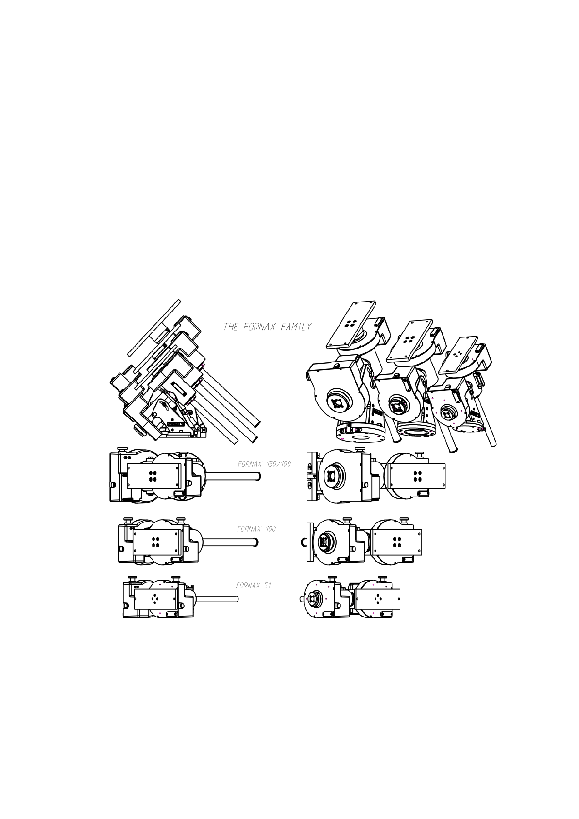
FORNAX 5x: FORNAX 51, FORNAX 52, FORNAX 55
FORNAX 10x: FORNAX 100, FORNAX 101, FORNAX 102, FORNAX 105
FORNAX 15x: FORNAX150/100, FORNAX 100, FORNAX 101, FORNAX 102, FORNAX 105

Introduction to the mechanics
Fornax mechanics are designed for precise movement of medium and large telescopes.
Constructed entirely of stainless metal materials, the housing is sealed against dust and water, so
there's no need to worry about delicate and sensitive parts of the drive
and therefore a very long life without maintenance.
The mechanism is perfectly suited to the highest demands of today's astrophotography.
The basic models typically have a periodic error of +/- 5" (1 period 7.5 minutes), which can be
further improved by the use of closed-loop guiding and precise positioning encoders and control
electronics to manage them appropriately. The control electronics are not part of the mechanism.
Main types and tabular data of the mechanism
The different types of equatorial telescope mechanics (Fornax 5x, 10x, 15x) of the manufacturer
Fornax can be considered as identical in terms of end-use and operation.
The differences are in the physical dimensions, the design of the washer that holds the base of the
mechanics and the maximum permissible load resulting from the differences in size.
Detailed data are given in the annexes.
Before you start the installation, please familiarise yourself with the data and dimensions of your
mechanics, which you will find in the annex, as well as with the markings used.

The mechanics consist of the main parts as described in the size
data: the main pieces:
When assembling the telescope mechanism, pay special attention to the assembly due
to the heavy weight of the elements! They can cause an accident if dropped. Heavy
weights can only be moved by a sufficient number of people at a time. There is a risk of
pinching when assembling the components.
Select and use the correct tools for assembly according to the dimensions.
Take extra care to ensure that the binoculars and polar binoculars are always pointed
in a direction that does not face the Sun!
Symbols used in the instructions
Before you start, familiarise yourself with the icons used in this manual
WARNING: Warn of situations that could cause injury to yourself or others
CAUTION: draws attention to situations that may cause damage to your device
or other devices
CAUTION: draws attention to situations that may cause damage to your device
or other devices
- mechanics,
- support platform, support disc (column top)
- counterweight shaft.
WARNING
NEVER LOOK INTO THE SUN WITH BINOCULARS! THE INTENSE LIGHT OF THE
SUN CAUSES PERMANENT EYE DAMAGE! VIEW THE SUN ONLY THROUGH A
SUITABLE FILTER! NEVER USE SENSORS THAT CAN BE PLACED IN FRONT OF THE
EYE! DO NOT USE THE BINOCULARS TO PROJECT AN IMAGE OF THE SUN, AS THE
HEAT ACCUMULATING IN THE TUBE MAY DAMAGE THE BINOCULARS AND
CAUSE A FIRE HAZARD!

Assembling and preparing the mechanics for use
The first step in assembly is to fix the support disc (column top) for the mechanism to the pre-set
pillar of the appropriate size and load capacity by means of Allen screws through the hole in such a
way that the notch used for horizontal adjustment is located in a northerly direction.
For proper operation, try to position the washer as horizontally as possible and orient it
as accurately as possible according to the cardinal points.
In the next step, tighten the fixing bolts of the washer (pillar top).
The next step is to lift the mechanism onto the washer.
Attention! Due to the heavy weight of the mechanics, pay attention to the number of
persons allowed to lift and/or the load capacity of the hoist, crane, hoist.
The height of the pillar may require the prior installation of a safety mounting platform. When
setting up, pay attention to the safety limits and the load-bearing capacity of the platform, as well
as to a stable, tip-over-free set-up. Mount the mechanism on the pillar in such a way that the
horizontal adjusting nose, rotating around the vertical axis, is positioned in the slit of the support
pillar and faces north.
Mechanics on the washer

Insert the Allen screws with a chisel head corresponding to the threaded hole of the washer into
the grooved screw profile on both sides of the base of the mechanism and fix them in such a way
that the mechanism can be rotated around the vertical axis, but cannot fall off the pillar!
In the next step, insert a suitably sized allen or socket head cap screw into each of the 2
horizontally located threaded holes in the recessed part of the washer (pillar top). Do not drive
them in until they hit the nose, the threaded end of the screw should not touch the nose part. The
mechanism should be rotatable about its vertical axis until it strikes the nose in either direction.
The next step is to adjust the "height" of the mechanism to the geographic width.
Height adjustment begins by slightly loosening the Allen screws located in the grooves in the two
side walls. The height can be adjusted by turning the nut between the base plate and the side walls
of the mechanism up and down.
The next step is to unscrew a cap made of right-handed bakelite-like material on the part of the
mechanism marked with a red ring.
Threaded cap on the mechanism for alignment to the visual pole
If you have an (optional) polarscope, you can use it later for accurate polar alignment. Insert the
polarscope into the hole marked with a green arrow so that the eyepiece is on the outside. With
the cap off, you will be able to look through the hole or through the polarscope at the location
indicated by the green arrows when the axes are in the correct position. Adjust the position of the
mechanics using the handwheel knobs located on each half of the two mechanics.
The adjustment is correct when you can see through the hole in the mechanics at the position
indicated by the green arrow.
Once aligned to the correct pole (horizontal-vertical), drive the two allen or captive screws on
either side of the mechanical washer to reach and secure the nose. Tighten the two height-
locking allen screws previously loosened on the two holes. Tighten the tapl fixing screws.
Replace and screw in the pole cap made of bakelite-like material.
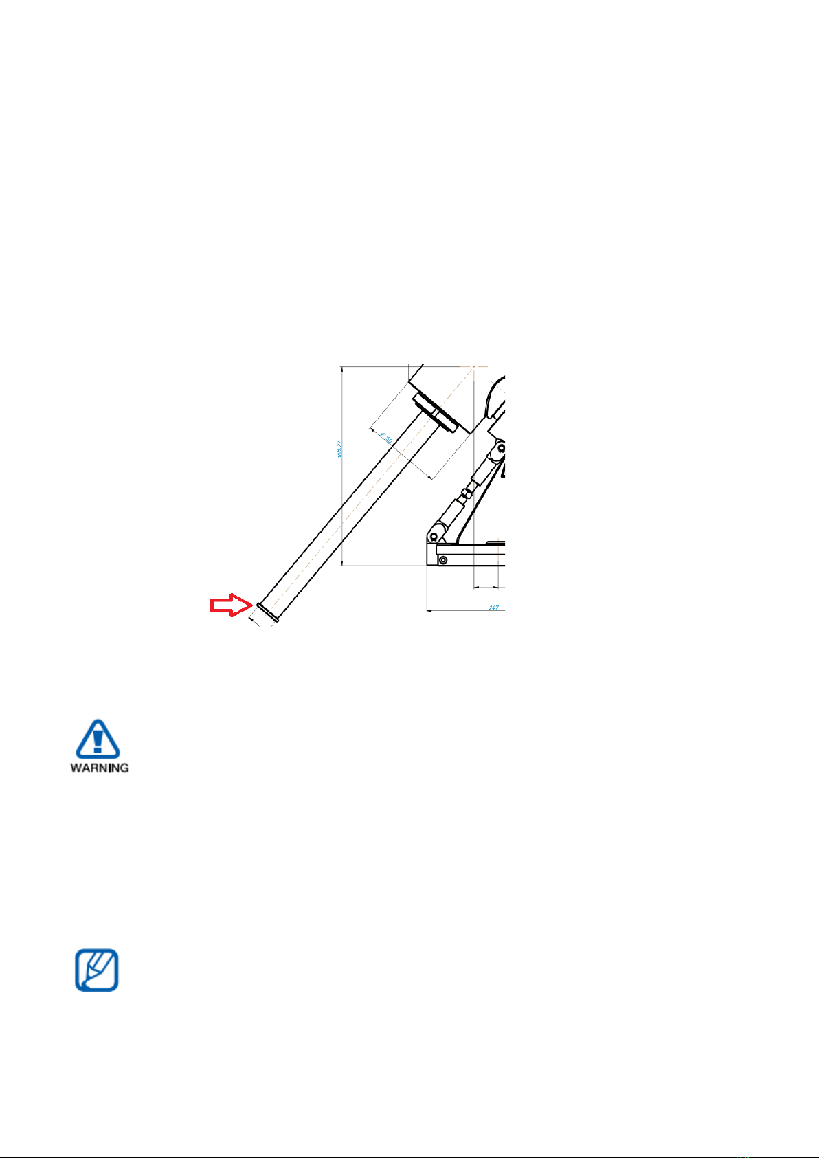
The next step is to install the counterweight shaft.
Screw the counterweight shaft into the mechanism until it is fixed.
Unscrew the "anti-fall" serrated screw (red arrow) at the end of the counterweight shaft to allow
the counterweights to be mounted on the shaft.
Due to the heavy weight of the counterweights, be careful when dropping or putting
them on, they may cause injury!
When installing the counterweights, tighten the counterweight fixing screws with sufficient
torque to ensure that they do not fall off after installation.
After the correct number and weight of counterweights have been installed, always tighten the
"anti-drop" notched screw (marked with a red arrow) properly.
In the next step, place and properly secure the telescope on the platform.
For the long and proper functioning of the mechanism, always balance the payload and
counterweights according to the rules of the trade.

SPECIFICATIONS
Mount weight 35 kg
Max payload capacity: 50kg (counterweight excluded)
Photographic payload: 30 kg (counterweight excluded)
Overall dimensions: 220 x 470 x 540 mm
Shaft diameter: 60mm, anodised aluminium alloy
Bearings: diameter 95mm, high precision tapered roller bearings in X layout
Gear: diameter 194mm, 1 modul, bronze, 192 teeth
Worm: diameter 22mm, multiple thread, grinded, hardened, corrosion proof steel (KO13)
Periodic Error: < +/- 6 arc seconds
Periodic Error (with encoders): < +/- 0.5 arc seconds
Stepper Motors: 200-phase step / rev., 1.3Nm
Voltage and Current: 12V DC, 3.5A peak power consumption at max. load
Step-resolution: 0.25 arc seconds / step with MC3 and 0,03 arc seconds / step with OC5
Maximum speed: 4 degrees / second
Counterweight holder shaft: diameter: 33.7mm (1,3267” KO33 tube) and length 470mm
SPECIFICATION OF FORNAX 5x EQUATORIAL MOUNT
SPECIFICATION OF FORNAX 10x EQUATORIAL MOUNT
Mount weight 50 kg
Max payload capacity: 90 kg (counterweight excluded)
Photographic payload: 70 kg (counterweight excluded)
Overall dimensions: 270 x 696 x 525 mm
Shaft diameter: 80 mm, anodised aluminium alloy
Bearings: diameter 125mm, high precision tapered roller bearings in X layout
Gear: diameter 242.5mm, 1.25 modul, bronze, 192 teeth
Worm: diameter 33mm, multiple thread, grinded, hardened, corrosion proof steel (KO13)
Periodic Error: < +/- 6 arc seconds
Periodic Error (with encoder): < +/- 0.5 arc seconds
Stepper Motors 200-phase step / rev., 1.7Nm
Voltage and Current: 24V DC, 3.5A peak power consumption at max. load
Step-resolution: 0.25 arc seconds / step with MC3 and 0,03 arc seconds / step with OC5
Maximum speed: 4 degrees / second
Counterbalance holder tube: diameter 42.4mm (1.25” KO33 tube) x length 570mm
SPECIFICATION OF FORNAX 15x EQUATORIAL MOUNT
Mount weight 70 kg
Max payload capacity: 120 kg (counterweight excluded)
Photographic payload: 90 kg (counterweight excluded)
Overall dimensions: 320 x 584 x 770 mm
Shaft diameter: 100mm, anodised aluminium alloy
Bearings: diameter 150mm, high precision tapered roller bearings in X layout
Gear: diameter 292.5mm, 1.5 modul, bronze, 192 teeth
Worm: diameter 33mm, multiple thread, grinded, hardened, corrosion proof steel (KO13)
Periodic Error: < +/- 6 arc seconds
Periodic Error (with encoders): < +/- 0.5 arc seconds
Stepper Motors 200-phase step / rev., 1.7Nm
Voltage and Current: 24V DC, 3.5A peak power consumption at max. load
Step-resolution: 0.25 arc seconds / step with MC5 and 0,03 arc seconds / step with OC5
Maximum speed: 4 degrees / second
Counterbalance holder tube: diameter 42.4mm (1.25” KO33 tube) x length 570mm

Dimension drawings Fornax 5x
Fornax 5x mechanics sizes
Fornax 5x platform dimensions

Fornax 5x pillar washer (pillar roof) dimensions

Fornax 10x
Fornax 10x mechanika méretek
Fornax 10x mechanics sizes
Ce manuel convient aux modèles suivants
10
Table des matières


