Forcepoint C1015 Instructions d'installation

Sidewinder Control
Center
Hardware Guide
Models C1015, C2050, and C3000
Revision D

2
Table of contents
Preface...................................................................................................................................... 3
Find product documentation.......................................................................................................................... 3
1 Introducing the appliances................................................................................................................................. 4
Model features................................................................................................................................................4
Network ports................................................................................................................................................. 7
Remote Management Module port................................................................................................................ 7
Replaceable hardware components.............................................................................................................. 8
Regulatory information................................................................................................................................... 8
2 Using the Remote Management Module........................................................................................................... 9
Configure the Remote Management Module................................................................................................ 9
Connect to the Remote Management Module web interface......................................................................10
3 Performing hardware maintenance tasks....................................................................................................... 11
Replace a hard drive................................................................................................................................... 11
Replace a power supply.............................................................................................................................. 12
Re-imaging the appliance............................................................................................................................ 12
Running hardware diagnostics.....................................................................................................................12
Interpreting system indicator lights.............................................................................................................. 13

Preface | 3
Preface
This guide provides the information you need to configure, use, and maintain your product.
Find product documentation
On the Forcepoint support website, you can find information about a released product, including product
documentation, technical articles, and more.
You can get additional information and support for your product on the Forcepoint support website at https://
support.forcepoint.com. There, you can access product documentation, Knowledge Base articles, downloads,
cases, and contact information.
Introducing the appliances | 4
Introducing the appliances
Models C1015, C2050, and C3000 support Forcepoint™ Sidewinder® Control Center version 5.1.0 and later.
Model features
Control Center appliances provide different maintenance and remote management features.
The following table provides an overview of the models.
Table 1: Model features
Model Hard drives Power supplies Remote Management Module Rack height
C1015 1 1 No
C2050 2 (RAID 1)
C3000 4 (RAID 5)
2 Yes
1U
Model C1015 features
Model C1015 has the following external features.
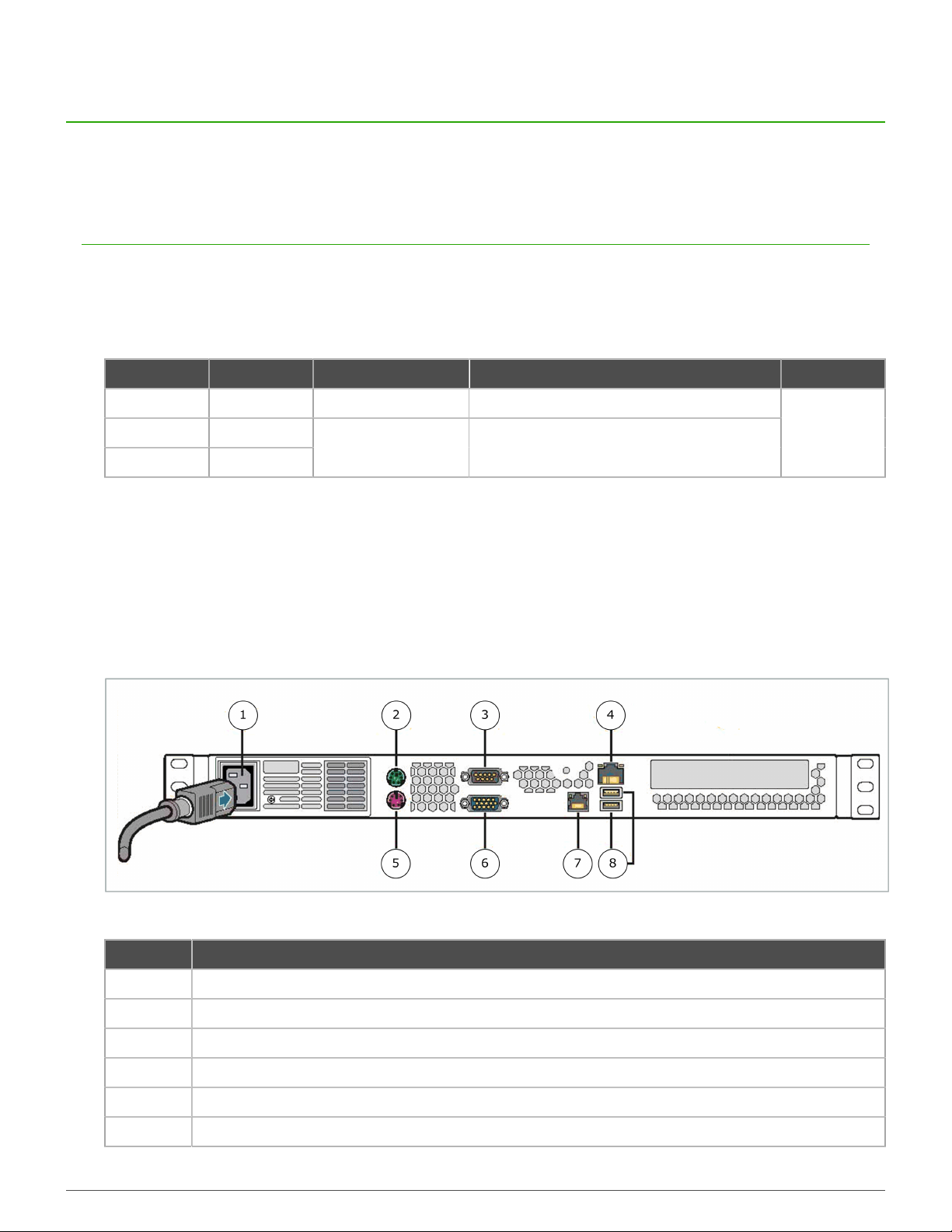
C1015 rear panel
The rear panel of model C1015 houses the AC power connector, keyboard and monitor ports, and network ports.
Figure 1: Rear panel of model C1015
Number Description
1 AC power connector
2 PS/2 mouse port
3 Serial port
4 Default network port (eth0)
5 PS/2 keyboard port
6 VGA port

Introducing the appliances | 5
Number Description
7 Network port (eth1)
8 USB ports
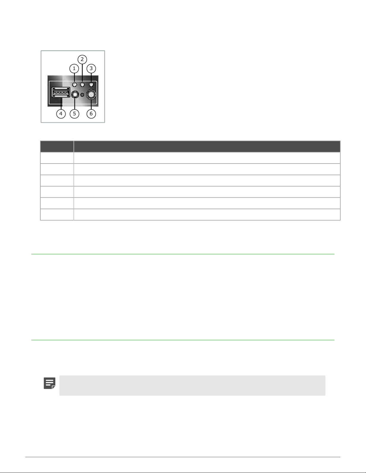
C1015 front panel
The front panel of model C1015 houses the power button and system indicator lights.
Figure 2: Front panel of model C1015
Number Description
1 USB port
2 Power button
3 System status indicator light
4 System power indicator light
5 Hard drive activity indicator light
6 NIC 1 activity indicator light
7 NIC 2 activity indicator light

Introducing the appliances | 6
Model C2050 and C3000 features
Models C2050 and C3000 have the following external features.
C2050 and C3000 rear panel
The rear panel of models C2050 and C3000 houses network ports and replaceable power supplies.
Figure 3: Rear panel of models C2050 and C3000
Number Description
1 System identification indicator light
2 System status indicator light
3 RJ-45 serial B connector (RS-232 serial port)
4 VGA port
5 USB ports
6 Default network port (eth0)
7 Network port (eth1)
8 Remote Management Module port
9 Power supply 1 status indicator light
10 Power supply 1
11 Power supply 1 AC connector
12 Power supply 2 status indicator light
13 Power supply 2
14 Power supply 2 AC connector
Introducing the appliances | 7
C2050 and C3000 front panel
The front control panel of models C2050 and C3000 houses the power button and system status indicator lights.
Figure 4: Front panel of models C2050 and C3000
Number Description
1 System identification indicator light
2 System status indicator light
3 Power/sleep indicator light
4 USB port
5 System identification button
6 Power button
Network ports
C1015 appliances have one network port. C2050 and C3000 appliances have two network ports.
Network ports provide network connectivity for activities such as:
• Managing Forcepoint Sidewinder appliances
• Managing the Control Center appliance using the Control Center Client application
• Streaming log data to remote servers, such as syslog servers.
Remote Management Module port
Models C2050 and C3000 have a Remote Management Module port.
The Remote Management Module provides system management features independent from the Control Center
operating system.
Note: The Remote Management Module cannot be used by Control Center and the port does not
appear in the list of interfaces.
You can use the Remote Management Module web interface to:
• View system information
• View system health, including:
• Sensor readings

Introducing the appliances | 8
• Event logs
• Control the appliance remotely using console redirection
• Turn the appliance on or off
Replaceable hardware components
Models C2050 and C3000 have replaceable power supplies and hard drives.
These components are hot-swap capable, so they can be installed or uninstalled while the appliance is operating.
Note: Model C1015 does not have any user-replaceable hardware components.
Regulatory information
In compliance with FCC regulations, this section provides information about the appliance models and contact
information.
Model information
The following regulatory information applies to models C1015, C2050, and C3000.
Table 2: Regulatory model information
Model Regulatory model
C1015 SR1530
C2050 SR1625
C3000 SR1625
Contact information
Use the following information to contact us.
Forcepoint LLC
10900-A Stonelake Blvd
Quarry Oaks 1, Ste 350
Austin, TX 78759
USA
+1-800-723-1166

Using the Remote Management Module | 9
Using the Remote Management Module
Use the Remote Management Module to view appliance information independently of the Control Center Client
application.
Configure the Remote Management Module
Use the BIOS to enable and configure the Remote Management Module. The module is disabled by default.
If the appliance is deployed in a production environment, schedule a maintenance interval to enable the Remote
Management Module.
Note: Model C1015 does not include the Remote Management Module.
1. Connect the Remote Management Module port to a network.
2. Enter the appliance BIOS menu.
1. Restart or turn on the appliance.
2. Press F2 to enter the BIOS menu.
3. Navigate to the Server Management tab.
4. Select BMC LAN Configuration.
Note: BMC configuration is not supported. If you want to configure BMC, use a different
IP address for Control Center and BMC configuration. If you use the same address, the
neighboring devices might display incorrect entries in the ARP table.
3. In the Intel RMM3 LAN configuration area, configure the following options:
• IP address
• Subnet mask
• Gateway IP address
Note: Do not configure the Baseboard LAN configuration area.
4. In the User configuration area, define at least one user that will be allowed to access the appliance from a
remote host.
1. In the User ID field, select the user ID that you want to configure.
Note: The appliance has five user IDs for user information: anonymous, root, User3,
User4, and User5. Each user ID can be enabled or disabled and assigned a privilege.
These users have no connection to the Control Center software.
2. Configure the following options:
• Privilege
• User name
• User password
3. In the User status field, select Enable to activate the user ID.
5. Press F10 to exit the BIOS and save the changes.
Using the Remote Management Module | 10
Connect to the Remote Management Module
web interface
Connect to the Remote Management Module web interface from a remote computer.
1. In a web browser, navigate to https://<IP of Remote Management Module>. The first time you
connect, accept the SSL certificate.
2. Specify a user name and password, then click Login. The home page appears.
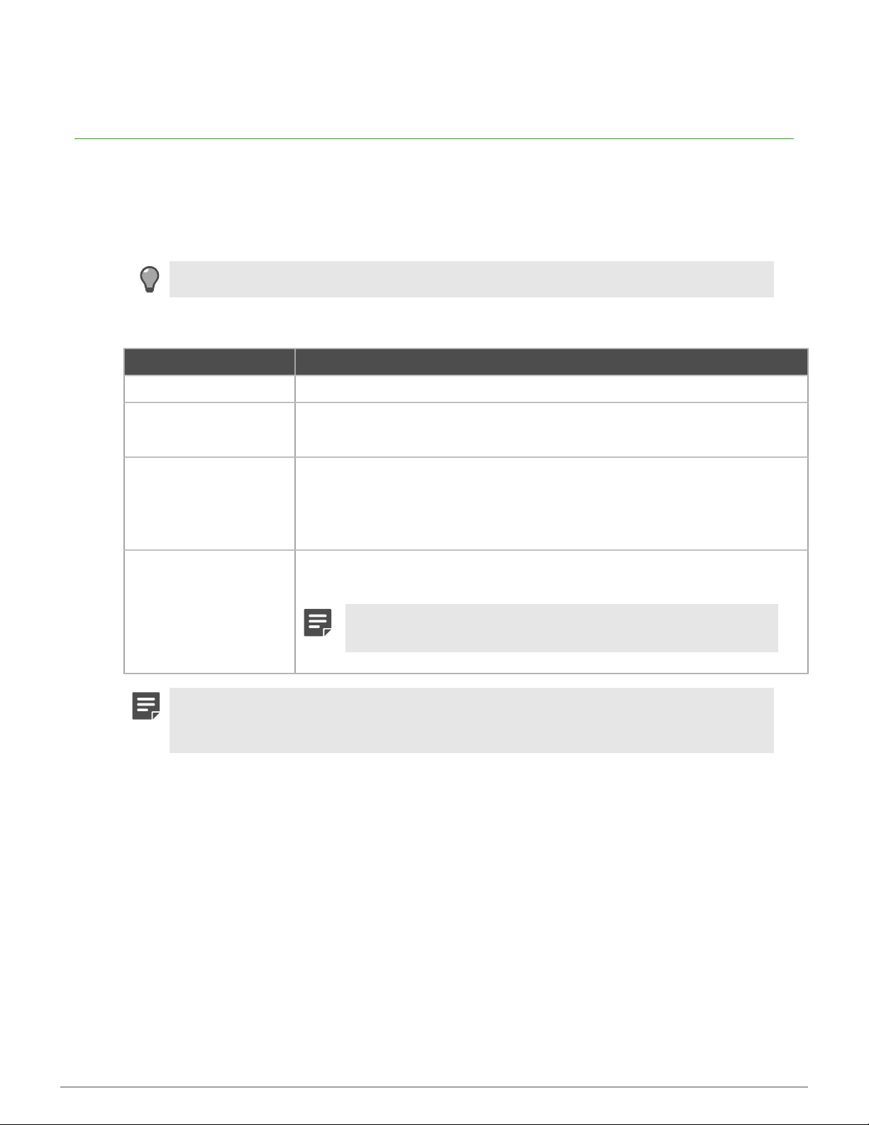
3. Click the tab that corresponds to the task that you want to perform.
Tip: For option definitions, click Help.
Table 3: Web interface tabs
Tab Task
System Information View appliance information.
Server Health • View sensor readings.
• View the event log.
Configuration • Configure Remote Management Module network settings.
• Manage Remote Management Module users.
• Upload a new SSL certificate.
• Configure LDAP (Lightweight Directory Access Protocol).
Remote Control • Access the appliance console.
• Turn the appliance on or off.
Note: To use console redirection you must allow the pop-up
window to open, then download the Java applet.
Note: When modifying network settings for the Remote Management Module on the
Configuration tab, select Intel(R) RMM3 from the LAN Channel drop-down list. Do not
configure the Baseboard Management LAN channel.
Ce manuel convient aux modèles suivants
2
Table des matières


