Flyzone DHC-2T Turbo Beaver Manuel utilisateur

INSTRUCTION MANUAL
WARNING: This product may use a lithium polymer (LiPo) battery. Improper handling may result in FIRE! You are responsible for following all
safety precautions as outlined in this instruction manual.
READ THROUGH THIS MANUAL BEFORE STARTING CONSTRUCTION.
It contains important instructions and warnings concerning the assembly and use of this model.
58526 FLZA4034
®
Length: 40.5 in
[1029 mm]
Radio: 5+ channel radio
system required
Motor: D4011–
920 kV,
40A ESC
11 x 7.5
3-blade prop
Wingspan: 59.5 in
[1510mm]
Wing
Area:
430 in2
[27.7 dm2]
Weight: 48.2 – 53.2 oz
[1367–1508 g]
Wing
Loading:
16.1– 18 oz/ft2
[49 – 54 g/dm2]

2
NOTICE
All instructions, warranties and other collateral
documents are subject to change at the sole discretion
of Horizon Hobby, LLC. For up-to-date product
literature, visit www.horizonhobby.com and click on the
support tab for this product.
Meaning of Special Language
The following terms are used throughout the product
literature to indicate various levels of potential harm when
operating this product:
WARNING: Procedures, which if not properly followed,
create the probability of property damage, collateral
damage, and serious injury OR create a high probability
of supercial injury.
CAUTION: Procedures, which if not properly followed,
create the probability of physical property damage AND
a possibility of serious injury.
NOTICE: Procedures, which if not properly followed,
create a possibility of physical property damage AND
little or no possibility of injury.
WARNING: Read the ENTIRE instruction manual
to become familiar with the features of the product
before operating. Failure to operate the product
correctly can result in damage to the product, personal
property and cause serious injury.
This is a sophisticated hobby product. It must be
operated with caution and common sense and requires
some basic mechanical ability. Failure to operate this
Product in a safe and responsible manner could result
in injury or damage to the product or other property.
This product is not intended for use by children without
direct adult supervision. Do not use with incompatible
components or alter this product in any way outside
of the instructions provided by Horizon Hobby, LLC.
This manual contains instructions for safety, operation
and maintenance. It is essential to read and follow all
the instructions and warnings in the manual, prior to
assembly, setup or use, in order to operate correctly
and avoid damage or serious injury.
14+
AGE RECOMMENDATION: Not for children
under 14 years. This is not a toy.
SAFETY PRECAUTIONS
& WARNINGS
As the user of this product, you are solely responsible for
operating in a manner that does not endanger yourself and
others or result in damage to the product or the property
of others.
●Always keep a safe distance in all directions around
your model to avoid collisions or injury. This model
is controlled by a radio signal subject to interference
from many sources outside your control. Interference
can cause momentary loss of control.
●Always operate your model in open spaces away from
full-size vehicles, trafc and people.
●Always carefully follow the directions and warnings
for this and any optional support equipment (chargers,
rechargeable battery packs, etc.).
●Always keep all chemicals, small parts and anything
electrical out of the reach of children.
●Always avoid water exposure to all equipment not
specically designed and protected for this purpose.
Moisture causes damage to electronics.
●Never place any portion of the model in your mouth as
it could cause serious injury or even death.
●Never operate your model with low transmitter batteries.
●Always keep aircraft in sight and under control.
●Always use fully charged batteries.
●Always keep transmitter powered on while aircraft is
powered.
●Always remove batteries before disassembly.
●Always keep moving parts clean.
●Always keep parts dry.
●Always let parts cool after use before touching.
●Always remove batteries after use.
●Always ensure failsafe is properly set before ying.
●Never operate aircraft with damaged wiring.
●Never touch moving parts.
1. Your Turbo Beaver airplane should not be considered a toy,
but rather a sophisticated, working model that functions very
much like a full-size airplane. Because of its performance
capabilities, the Turbo Beaver, if not assembled and
operated correctly, could possibly cause injury to yourself
or spectators and damage to property.
2. You must assemble the Turbo Beaver airplane according
to the instructions. Do not alter or modify the model, as
doing so may result in an unsafe or unyable model. In
a few cases the instructions may differ slightly from the
photos. In those instances the written instructions should
be considered as correct.
3. If you are not an experienced pilot or have not own
this type of model before, we recommend that you get
the assistance of an experienced pilot in your R/C club
for your rst ights. If you’re not a member of a club, your

3
local hobby shop has information about clubs in your area
whose membership includes experienced pilots.
4. Check the operation of the model and all components
before each ight.
5. DO NOT install the propeller UNTIL you have
completed ALL FOUR of the following steps!
A. You MUST conrm that the radio system is functioning
properly.
B. Understand the operation of the motor/failsafe/ESC
in all possible operation scenarios.
C. Learn how to properly power up and power down for
each ight (see back page).
D. Complete all of the steps in this manual, prior to the
prop installation on page 18.
Install the propeller only AFTER you have completed
these four steps.
6.
While this kit has been ight tested to exceed normal use,
if the plane will be used for extremely high stress ying, or
if a motor or battery larger than ones in the recommended
range is used, the modeler is responsible for taking steps to
reinforce the high stress points and/or substituting hardware
more suitable for the increased stress.
We, as the kit manufacturer, provide you with a top quality,
thoroughly tested kit and instructions, but ultimately
the quality and yability of your nished model depends
on how you build it; therefore, we cannot in any way
guarantee the performance of your completed model,
and no representations are expressed or implied as to
the performance or safety of your completed model.
Remember: Take your time and follow the instructions
to end up with a well-built model.
TABLE OF CONTENTS
NOTICE . . . . . . . . . . . . . . . . . . . . . . . . . . . . . . . . . . . . . . . 2
Meaning of Special Language . . . . . . . . . . . . . . . . . . 2
SAFETY PRECAUTIONS & WARNINGS . . . . . . . . . . . . . 2
INTRODUCTION . . . . . . . . . . . . . . . . . . . . . . . . . . . . . . . . 4
Academy of Model Aeronautics. . . . . . . . . . . . . . . . . 4
REQUIRED TO COMPLETE . . . . . . . . . . . . . . . . . . . . . . . 4
Radio System . . . . . . . . . . . . . . . . . . . . . . . . . . . . . . . 4
Battery and Charger . . . . . . . . . . . . . . . . . . . . . . . . . . 4
CONTENTS . . . . . . . . . . . . . . . . . . . . . . . . . . . . . . . . . . . . 5
KIT INSPECTION . . . . . . . . . . . . . . . . . . . . . . . . . . . . . . . 5
ORDERING REPLACEMENT PARTS. . . . . . . . . . . . . . . . 5
ASSEMBLY . . . . . . . . . . . . . . . . . . . . . . . . . . . . . . . . . . . . 6
Mount the Landing Gear. . . . . . . . . . . . . . . . . . . . . . . 6
Mount the Floats. . . . . . . . . . . . . . . . . . . . . . . . . . . . . 6
Mount the Horizontal and Vertical Stabilizer . . . . . . . 8
Mount the Wings. . . . . . . . . . . . . . . . . . . . . . . . . . . . . 9
Install the Battery . . . . . . . . . . . . . . . . . . . . . . . . . . . 10
Receiver Installation . . . . . . . . . . . . . . . . . . . . . . . . . 11
Failsafe Setting and Function. . . . . . . . . . . . . . . . . . 11
Tactic Failsafe Procedure . . . . . . . . . . . . . . . . . . . . . 11
Testing the Failsafe . . . . . . . . . . . . . . . . . . . . . . . . . . 11
ESC Operation/Startup. . . . . . . . . . . . . . . . . . . . . . . 12
Center the Control Surfaces. . . . . . . . . . . . . . . . . . . 11
FINAL FLIGHT PREPARATION. . . . . . . . . . . . . . . . . . . . 17
Check the Control Throws . . . . . . . . . . . . . . . . . . . . 17
Motor and Prop Safety Precautions. . . . . . . . . . . . . 18
Mount the Propeller and Spinner . . . . . . . . . . . . . . . 18
Check the Center of Gravity (C.G.). . . . . . . . . . . . . . 19
FLYING. . . . . . . . . . . . . . . . . . . . . . . . . . . . . . . . . . . . . . . 19
REPAIRS . . . . . . . . . . . . . . . . . . . . . . . . . . . . . . . . . . . . . 20
LIMITED WARRANTY . . . . . . . . . . . . . . . . . . . . . . . . . . . 21
CONTACT INFORMATION. . . . . . . . . . . . . . . . . . . . . . . . 22
POWERING UP . . . . . . . . . . . . . . . . . . . . . . . . . . . . . . . . 23

4
INTRODUCTION
Thank you for purchasing the Flyzone 1/10th-scale de
Havilland DHC-2T Turbo Beaver Rx-R airplane. For anybody
who enjoys ying oat planes or who aspires to do so for
the rst time, the Flyzone Turbo Beaver is the perfect choice
because it ies off the water so well—you virtually can’t
mess up a takeoff or landing unless you try! Of course, the
Turbo Beaver is almost just as much at home on dry land
as it is in the water. And with the aps extended you can
set your Turbo Beaver down on water or on land as light
as a feather.
For the latest technical updates or manual corrections to
the Turbo Beaver airplane, visit the Flyzone site at www.
yzoneplanes.com. Open the “Airplanes” link, then select
the “Turbo Beaver”.
Academy of Model Aeronautics
If you are not already a member of
the AMA, please join! The AMA is the
governing body of model aviation and
membership provides liability insurance coverage, protects
modelers’ rights and interests and is required to y at most
R/C sites.
Academy of Model Aeronautics
5151 East Memorial Drive Tele. (800) 435-9262
Muncie, IN 47302-9252 Fax (765) 741-0057
Or via the Internet at: http://www.modelaircraft.org
IMPORTANT: Two of the most important things you can
do to preserve the radio controlled aircraft hobby are to
avoid ying near full-scale aircraft and avoid ying near or
over groups of people.
REQUIRED TO COMPLETE
Other than a #1 and #2 Phillips screwdriver, and a few drops
of non-permanent threadlocker (GPMR6060), no adhesives
or anything extraordinary is required to assemble the Turbo
Beaver airplane.
Radio System
The model requires a transmitter and receiver with at least 5
channels. For an economical, digital 6-channel transmitter
we recommend the Spektrum DX6 or DX6e. Both are budget
friendly models loaded with options that are more than
adequate for ying this model. The Tactic TTX660 is another
affordable computerized transmitter that would be a great
choice. Part numbers are provided:
❍Tactic TTX660 6-Channel Computer Transmitter
(TACJ2660)
❍Tactic TR625 6-Channel SLT Receiver Twin Antennas
(TACL0625)
❍DX6 6-Channel DSMX Transmitter Gen 3 with AR6600T
Receiver (SPM6755)
❍Spektrum DX6e 6-Channel Radio with AR610 Receiver
(SPMJ1006)
Battery and Charger
A 3S 11.1V LiPo battery is required. A commonly used
2200mAh sized pack provides a good balance between
ight time and performance. A charger capable of safely
charging LiPo battery chemistry is also required. Onyx and
Dynamite both offer a variety of models from your basic,
economically priced chargers all the way to your high-
end, feature rich models that will accommodate all of your
foreseeable charging needs.
❍
11.1V 2200mAh 3S 30C LiPo, EC3 (EFLB22003S30)
❍
F-Tek 2200mAh 3S 11.1V 40C LiPo EC3 LED
(KXSB22003S40)
IMPORTANT:
This model is equipped with an E-ite EC3
connector. If your charger does not include EC3 charge
leads, they can be purchased separately using part number
EFLAEC312.

5
KIT INSPECTION
Before assembly, take an inventory of this kit to make
sure it is complete, and inspect the parts to make sure
they are of acceptable quality. If any parts are missing or
are not of acceptable quality, or if you need assistance
with assembly, contact Product Support. When reporting
defective or missing parts, use the part names exactly as
they are written in the Contents list.
Horizon Hobby Service Center Ph: (877) 504 0233
1608 Interstate Dr.
Champaign, IL 61821
E-mail: productsupport@horizonhobby.com
ORDERING REPLACEMENT PARTS
Replacement parts for the Flyzone Turbo Beaver
Rx-R
airplane are available using the order numbers in the
Replacement Parts List that follows. The fastest, most
economical service can be provided by your hobby dealer
or mail-order company.
To locate a hobby dealer, visit the Flyzone web site at www.
yzoneplanes.com. Click on the Storefront icon at the top
of the page to load the Flyzone Dealer Locator. Follow the
instructions provided on the page to locate a U.S., Canadian
or International dealer.
Order No.
REPLACEMENT PART LIST
Description
FLZA6700
FLZA6701
FLZA6702
FLZA6703
FLZA6704
FLZA6705
FLZA6706
FLZA6707
FLZA6708
FLZA6709
FLZA6710
FLZA6711
FLZA6276
FLZA6284
FLZA6554
FLZA6270
FLZA6277
FLZA6278
EFLA1040U
SPMSA330R
EFL5962
FLZA6288
Fuselage
Wing
Horizontal Stabilizer
Vertical Fin
Landing Gear
Cowl
Floats
Hatches
Spinner
Prop Adapter
Motor
Decal
Float Brackets
Wing Strut Set
Tundra Wheel
Tail Wheel Set
Water Rudders
Wing Clips
40A Brushless ESC
9 Gram Servo Reversed
11 X 7.5 Propeller, 3-blade
Lighting Set
CONTENTS
1.
2.
3.
4.
5.
6.
7.
8.
9.
10.
11.
12.
Fuselage
Left Wing
Right Wing
Main Landing Gear
Float Brackets
Wing Struts
Vertical Stabilizer
Hardware
Propeller/Spinner Assembly
Top Hatch
Horizontal Stabilizer
Floats
1
6
7
2
4
8
9
10
11
12
3
75

6
ASSEMBLY
It’s your choice to install either the landing gear or the oats.
Start the assembly after making this decision.
Mount the Landing Gear
❑ 1.
Use a #2 Phillips screwdriver to fasten both main landing
gears to the fuselage with three M3x16 screws in each side.
❑ 2. Mount the tail gear with two M2.5x8 screws, then fasten
the pushrod wires as shown. Make sure the tail wheel is
perpendicular with the steering arm and tighten the screws.
Mount the Floats
❑ 1. Connect the oats to each other with the horizontal
struts and four M2.5x20 machine-thread screws.

7
❑ 2. Use eight M2.5x8 screws to fasten the braces to the
oats, matching the labels printed or molded into the end
of each brace to each mount location on each oat.
❑ 3. Fasten the oat braces to the fuselage with one
M3x16mm screw and two M2.5x8mm screws in each side
of the fuselage. No screw is installed in the third strut at
this time.
❑ 4. Connect a small rubber band to the inside side of
each oat and water rudder as shown.
❑ 5. Fasten the wire hooks on the end of each rudder
line to the connectors in the steering arm. As best as
you can, adjust the tension in the lines to center the
water rudders—the rudders don’t have to be perfectly
centered, because over time they may drift anyway, and
the rudders are forgiving and overall water handling is easy.
TIP: One of the wire hooks will need to be bent up some
to not interfere with the other hook.

8
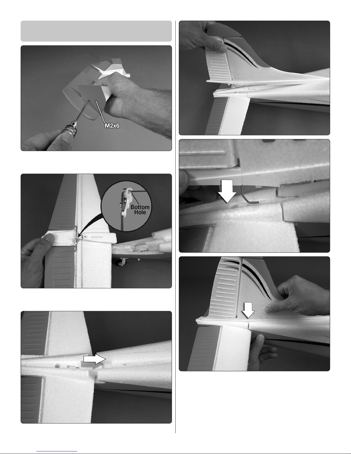
Mount the Horizontal
and Vertical Stabilizer
❑ 1. Fasten the vertical stabilizers to each end of the
horizontal stabilizer (stab) with M2x6 screws.
❑ 2. Connect the elevator pushrod to the bottom hole in
the elevator horn as shown.
❑ 3. Rotate the stab upward and key it into the fuselage.
❑ 4. Key the rudder torque rod down into the receptacle
while tting the vertical stabilizer (n) into the fuselage.
Tightly press the assembly down into position.

9
❑ 5. Secure the stab and n with the M3x22 screw.
Mount the Wings
❑ 1. Fasten the wing clips to both sides of the fuselage
with four M3x10 screws.
❑ 2.
Guide the wires from the right wing into the fuselage,
then slide the wing joiner tube and the ap pushrod wire
through the corresponding holes. Also guide the ap pushrod
wire into the screw-lock connector on the ap servo. Guide
the joiner tube through the hole in the left side of the fuselage,
then tightly “CLICK!” the wing onto the wing clips.

10
❑ 3. Mount the left wing the same way.
❑ 4. Mount the top of each wing strut to the wing with a
M2.5x8 machine-thread screw.
❑ 5.
Mount the bottom of each strut to the fuselage over
the third oat strut (or over the main landing gear) with a
M3x16 screw.
Install the Battery
❑ 1. Cut two 1" [25mm] strips from the rougher, “hook”
side of the included adhesive-back hook-and-loop material.
Apply the strips inside the fuselage where shown and press
them down tightly so they adhere.
❑ 2. Cut a 3" [ 76 mm] strip from the softer, “loop” side and
attach it to the battery so the larger “discharge” wires will
be on the right side as shown. (This will position the wires
opposite the receiver for a better t.)
Table des matières