FLYLINE MoCo Manuel utilisateur


Copyright © 2017 PhotoShip One LLC - www.PhotoShipOne.com2
© 2017 PhotoShip One, LLC. All rights reserved.
PhotoShip One, LLC!
Mesa, AZ 85209!
USA
www.photoshipone.com
!
Except as expressly provided herein, no part of this guide may be
reproduced, transmitted, disseminated, downloaded or stored in
any storage medium, for any purpose without the express written
permission of PhotoShip One. PhotoShip One grants permissions to
download a single copy of this guide onto an electronic storage
medium to be viewed for personal use, provided that the complete
text of this copyright notice is retained. Unauthorized commercial
distribution of this manual or any revision hereto is strictly
prohibited.
IN NO EVENT, SHALL PHOTOSHIP ONE, LLC BE LIABLE FOR ANY
INCIDENTAL, SPECIAL, INDIRECT OR CONSEQUENTIAL DAMAGES,
WHETHER RESULTING FROM THE USE, MISUSE OR INABILITY TO
USE THE PRODUCT OR FROM DEFECTS IN THE PRODUCT.

Copyright © 2017 PhotoShip One LLC - www.PhotoShipOne.com3
MANUAL REVISION HISTORY
REVISION
DATE
COMMENTS
DOWNLOAD LINK
1
4/15/2017
Initial Release
X
2
05/23/2017
• Firmware version 1.1 changes
• Added Manual Revision History & Firmware Changelog
• Added DX6 switch location graphic
• Revised Ping-Pong Mode Operation
• Added AR8000 rx setup information
X
FIRMWARE CHANGELOG
VERSION
DATE
COMMENTS
1.0
4/15/2017
Initial Release
1.1
05/23/2017
• Remote entry/exit of Ping-Pong Mode
• Ping-Pong Mode Gain adjustment set to 1/2 of gain pot value
• Throttle values to accommodate control transmitters end-point value at 100%.
PWM scaling changed from 1000us/2000us to 1100us/1900us
• Serial Protocol Added
• 2 sec. Startup Delay added to prevent motor from spinning on power-up
• Fail Safe sensing added for AR610 rx
• LED light bug fixes
Copyright © 2017 PhotoShip One LLC - www.PhotoShipOne.com4
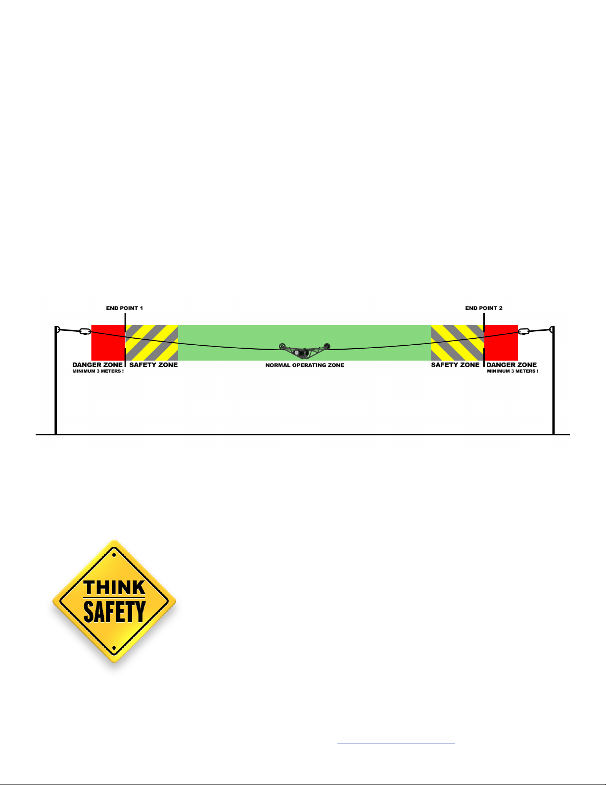
The MoCo Module allows the FlyLine trolley to ‘know’ its position on the rope. This is useful for
automatic control of the system.
The user can set endpoints at each end of the rope that the trolley will not cross when properly
configured.
The MoCo module also has an automatic ‘ping-pong’ mode which will automatically and
repeatedly drive the trolley between two user set end points at a user set speed. This is perfect
for live event coverage at concerts or festivals where you want continuous motion of the trolley
and only want a single operator to control the camera gimbal.
It is extremely important to follow these instructions carefully and
conduct operation in accordance with all local safety regulations and
best practices.
You MUST read thoroughly the Safety Section at the end of this
instruction manual before operation. If you are unsure of any part of
the operation of the MoCo, do NOT operate the system. Contact us for
assistance.
Improper operation of the system can result in damage to property
and/or injury/death to persons.

Copyright © 2017 PhotoShip One LLC - www.PhotoShipOne.com5
TABLE OF CONTENTS
1. INSTALLATION
1.1 Mount Sensor Disc to Outrigger Wheel
1.2 Mount Sensor to FlyLine Frame
1.3 Mount MoCo Module to FlyLine Frame
1.4 Connect RC Control Cables
1.5 Connect & Route Sensor Cable
2. MOTOR CONTROLLER SETUP
2.1 DIP Switch Assignments
2.2 Current Limiter Adjustment
2.3 Data Cable Connection
2.4 Connections Diagram AR610 rx
2.5 Connections Diagram AR8000 rx
2.6 Motor Wire Connections
3. SPEKTRUM CONTROLLER SETUP
3.1 Servo Setup > Reverse
3.2 Servo Setup > Travel
3.3 D/R and Expo
3.4 Switch Assign
3.5 Switch Assign Aux 2 (AR8000 rx only)
"
4. MODE SELECTION
4.1 End Point Mode
4.2 Ping-Pong Mode
4.3 Sensor Test Mode
"
5. OPERATION
5.1 Manual Control/Auto End Point Mode
5.2 Gain Calibration
5.3 Ping-Pong Mode

Copyright © 2017 PhotoShip One LLC - www.PhotoShipOne.com6
1. MOCO MODULE INSTALLATION
1.1 Mount Sensor Disc to Front Outrigger Wheel!
If looking at the FlyLine trolley with the motor controller and end of the motor facing you, the front of the
trolley is to your right.
Front
Attach the sensor disc to the outrigger wheel. Place the
spacer in between the wheel and the disc. Use 3x22 screws. !
!
We recommend using thread locking compound like Loctite.
1.2 Mount Sensor to FlyLine Frame!
The sensor mounts to the inside of the right side frame of the
FlyLine next to the front outrigger wheel. Use M3x10 screws.
You will notice there are two M3 tapped holes in the FlyLine frame
next to the wheel. The sensor has four hole selections that can be
used.
The hole selections used with the sensor depend which of the four
axle hole selections are used on the frame.
If the axle is in the lowest hole position on the frame, then use
top holes in the sensor. Conversely, if the axle is placed in the top
Sensor
Any other axle positions will correspond to the other holes in the sensor respectively. The idea is to keep the
sensor aligned with the axle of the outrigger wheel so that the sensor is properly aligned with the sensor disc
on the wheel.
The sensor cable should NOT be bent or flexed sharply. Bending or flexing
the cable near the ends can damage the connections inside the sensor or at
the connector. Handle the sensor cable gently.

Copyright © 2017 PhotoShip One LLC - www.PhotoShipOne.com7
1. MOCO MODULE INSTALLATION
1.3 Mount MoCo Module to FlyLine Frame
The MoCo module mounts to the right FlyLine frame with double sided tape. Place the module in the
position shown.
1.4 Connect RC Control Cables
Connect the RC control cables from the Spektrum AR610 to the left side of the MoCo as follows:
Position 1 on MoCo to Elev on receiver!
Position 2 on MoCo to Gear on receiver!
Position 3 on MoCo to Aux 1 on receiver!
Position 4 on MoCo to Thro on receiver
WHITE wires of the cables should
be oriented to the top of the MoCo.!
!
BLACK wires should be at the bottom. !
1.5 Connect & Route Sensor Cable
Connect the wheel sensor cable to the connector on the right side of the MoCo unit. Route the cable along
the trolley frame and secure with cable ties. The cable will need to route from the outside of the frame to
inside of the frame at the sensor. The cable can be flexed smoothly. Do NOT sharply bend or flex the cable!!
!
Failure to secure the cable properly could result in the cable being pulled from the sensor or MoCo
which could result in a dangerous crash. Be sure the cable is properly secured!
AR610 connections

Copyright © 2017 PhotoShip One LLC - www.PhotoShipOne.com8
5
2. MOTOR CONTROLLER SETUP
2.1 - DIP SWITCH ASSIGNMENTS!
In order for the MoCo unit to operate properly it is important
that the motor controller DIP switches be configured.
The DIP switches on the motor controller circuit board MUST
be configured with switches 1 & 2 in the ‘OFF’ position and
switches 3, 4, 5, 6 in the ‘ON’ position as shown below.
Look for the ‘ON’ printed on the DIP switch block above
switches 1 & 2. Switches flipped towards this direction are
‘ON’.
2.2 - CURRENT LIMITER ADJUSTMENT!
Locate the current limiter adjustment potentiometer on the
motor controller. It is blue with a yellow adjustment screw in
the middle.
Set the adjustment screw to 50% by rotating it so the arrow
portion of the screw points to the ’50’ on the motor controller
circuit board.
2.3 - Data Cable Connection!
Install the supplied Data Cable to the terminals on the motor controller marked 0V, 5V,
S1. !
!
Black wire connects to 0V!
Red wire connects to 5V!
White wire connects to S1
Connect the plug end of the data cable to Position 5 on the MoCo unit with the WHITE
signal wire on the top position, BLACK at the bottom.

Copyright © 2017 PhotoShip One LLC - www.PhotoShipOne.com9
2. MOTOR CONTROLLER SETUP
2.4 - Connections Diagram for Spektrum AR610!
When all connections are made the system should be as follows:
Verify RC controls and data cables are oriented correctly with WHITE, RED, BLACK wires in proper position.
S+ -

Copyright © 2017 PhotoShip One LLC - www.PhotoShipOne.com10
2. MOTOR CONTROLLER SETUP
2.5 - Connections Diagram for Spektrum AR8000/AR8010T!
When all connections are made the system should be as follows:
Verify RC controls and data cables are oriented correctly with WHITE, RED, BLACK wires in proper position.
S+ -
Table des matières


