Fly Wing H1 Manuel utilisateur

User Manual V2.2
2019.12
Heli
About H1
Overview
The H1 helicopter flight control system, with its built-in floating IMU and
double-layer damping sponge, combined with a new generation of control
and IMU algorithms, makes it easy to experience helicopters.
The H1 flight control system consists of a main controller
(built-in floating IMU, compass and barometer) and a dual-mode GPS
module.
System composition
The main controller is the core module of the flight control system. It uses IMU,
barometer, GPS and compass module to achieve precise attitude control and high-
precision positioning of the aircraft.
Use the H1 Assistant to configure parameters to the main controller, including
installation, flight control, and parameters of other external devices. The LED light
shows the current system status in real time, helping you to better understand the
current status of the flight control.
Component and port description
Flight Control (FC)
The FC has the following features:
1. 1. The FC has 5 PWM outputs, and one receiver input port. The PWM output
port is connected to three swash plate servos , main ESC and tail servo(tail
motor )
2. Built-in IMU and barometer to measure flight attitude and altitude, and with GPS to
achieve aircraft horizontal fixed point, thus achieving flight control.
3. Support multiple receiver ,receiver input supports PPM, S.bus and other
mainstream single-line mode, automatic identification.
4. Use TYPE-C plug, regardless of the positive and negative plug, easy to use.
H1 user manual

H1 user manual
FC SPCIFICATION AS FOLLOWS:
1. Pin port
Receiver,Servo,ESC plug
here
2. USB
TYPE-C port,connect
computer to adjustment
3.
4.
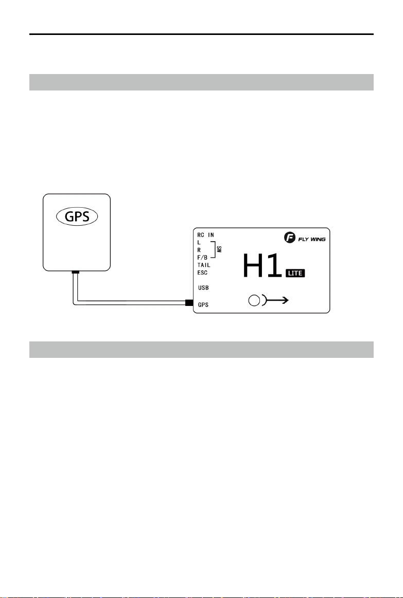
GPS port
GPS and external compass
interface
LED FC status Indicator
FC
Support swashplate Type:
HR3 H3
GPS module:
The GPS module includes a GPS/GLONASS dual-mode receiver and a compass. The
compass is used to measure the geomagnetic field and, together with GPS, achieves
the horizontal orientation of the aircraft. Calibrate the compass before use and avoid
storing and using it in a ferromagnetic environment。

INSTALL
Overview
Install procedure
Please read this section carefully and follow the procedure below to install and
set up your flight control system to ensure that the system works properly.
1 Ensure that the modules required for installation are complete .
2 Watch instructional video (www.flywingrc.com):
•Watch the installation demo and module connection video, install the FC
system to the aircraft and connect it properly.
•Watch the software assistant video, run the assistant , and complete the
parameter settings according to the software guide and embedded
instructions.
3 Check that the motor settings, remote channel settings, and protection
functions are set correctly.
4 Confirm that the individual devices connected to the FC are set correctly.
Take the FW450 as an example, the installation effect is as follows:
H
o
H1 user manual

Ready to install
relative devices
When use H1,Please prepare helicopter,transmitter system,ESC,servo and battery,ect
by yourself. Supported devices as follows:
A. Helicopter :H3 and HR3 swashplate;Main power is battery or oil;The rear is a
variable pitch or motor driven helicopter.
B. Servo:Support 1520us wide-duty servo as swashplate servo, support 1520us
wide frequency or 760us narrow frequency as the tail servo, the servo working
frequency is automatically recognized.
C. ESC:Main motor tail motor ESC support standard PWM ESC.
D. Receiver:Support S.bus protocol, PPM protocol, Graupner SUMD HD08 protocol
E. Battery:3-6S Lipo battery,support voltage check,with low voltage protection.
Download Assistant Software
Download software H1-Heli
Please visit the web to download:
https://www.flywingrc.com/software/
The assistant software needs to use Win7 and above. XP can be used, and some
compatibility problems may occur.
Install Assistant software
H1-Heli will guide you through the FC system's parameter
settings, please follow the steps below to install
Windows Installation and operation on the system:
Support Win7, Win8 , Win10(32 or 64-bit )system
1. Connect the TYPE-C USB port to your PC using the TYPE-C USB cable.
2. Run the H1-Heli driver installation package and follow the prompts to
install it.
3.Double-click the H1-Heli icon to run the assistant software.
3. For safety reasons, please remove the propeller or disconnect the
motor when adjusting.
H1 user manual
It is recommended to use Win10 64-bit operating system, which has
achieved the best experience.
If the software still indicates that the flight controller is not found, or the
communication interface failed to initialize, install the driver and restart the
computer or replace the data line and try again.

1. 1. Keep the GPS mark side up and the arrow pointing in the direction of the aircraft
nose, otherwise it will not fly normally.
2. 2. Please try to keep no tall buildings around and no trees, otherwise it will affect the
GPS module.
3. 3. The compass is a magnetic sensitive device and should be kept away from strong
magnetic fields, electric fields, and electromagnetic fields (such as wires).
4. The installation needs to select the appropriate GPS installation location to avoid
interference with the compass during operation.
Start the Installation
Important: Strictly follow the provided guidelines. Failure to do so may lead to
unexpected flight behavior or serious accidents.
Install FC
The FC is facing up and parallel to the fuselage,Mounting mark points to the
head direction,Center position as close as possible to the center of gravity of the
aircraft,Then use double-sided tape to fix it to the body.
Install GPS Module
The GPS module is horizontally parallel to the fuselage. GPS installation direction as
shown,fix the GPS to the mount with double-sided tape,The fixing seat is fixed on
the tail pipe by double-sided tape and cable tie. After installation, try to ensure that
the GPS module is level with the aircraft fuselage, the GPS is fixed firmly, and the
outlet and the nose are kept level.
GPS use requirements:
H1 user manual

H1 user manual
Face up,do not invert
If you want to use it under server cold condition, please do the insulation work.
It is recommended to install as close to the vibration as possible, parallel to the fuselage
The FC system is not waterproof, oil-proof, or dust-proof.
Check frequently to ensure that the double-sided tape is securely installed.
FC System Connection
Follow the instructions below to complete the connection,And use a plastic cable tie
to organize the connection to make it clean.
H1 is the metal shell, do not take the power to H1 or the carbon plate of H1
Aircraft equipment connection
When using H1, it is necessary to connect the receiver, ESC, battery and other related
aircraft equipment, and set their parameters in H1-Heli, otherwise it may not be able to
fly or even cause serious safety accidents.
Receiver
Different types of receiver connection interfaces are different, please connect
accordingly. After the connection is successful, the FC will automatically recognize the
signal and display the stick information on the software.

Transmitter Setting
1 Your transmitter must support "Fail-Safe" Setting the all the channel value of fail-safe by
yourself. Otherwise Fail-safe is not available.
2、Your transmitter working mode is "AIRPLANE"
3、All channels of the transmitter should work independently, disable Throttle curve and
Pitch curve
4、You need at least a 5 channel 3 segment switch to be used as a control mode switch, and
a 2channel 2 segment switch to stop and start the motor.
5.Mechanical setup first ,servo arms are 90 degree to the shaft and all the trims and Sticks
are at the centre. it should be 0 pitch at mid stick5
For Example as Futaba 14SG
1、Setting 7008 receiver as mode B(S.BUS 1), and Connect the flight controller to the S.BUS 1
interface of the receiver
2、The transmitter and the receiver are linked, set a new model , set as airplane model. no
mixing mode
H1 user manual
3、LINKAGE MENU --- FUNCTION 5 channel is set to 3-segment switch (SA),
corresponding to the Return mode --- GPS mode --- 3D manual mode; 7-channel is set to
2-segment switch (SF), corresponding to the shutdown of the motor And start; 8-channel is
set to 3-segment switch (SB), corresponding to the shutdown of semi-automatic flight ---
one-key circle fly-8-flight; 9-channel is set to 2-segment switch (SC), corresponding to
one-key reverse Fly forward and backward.
4、Enter FAIL SAFE mode and turn on 5-channel F / S. Turn the transmitter's 5-channel
switch (SA) to the Return, and press and hold the "RTN" key for 1 second at the POS
position. Then return to the main interface and observe in the software assistant software.
When the remote control is turned to the GPS position, turn off the remote control. Will the
mode switch prompt the loss of the remote control signal? Will other brands of remote
control automatically jump to the home position Bit, 7 channels stay on start.

H1 user manual
4,Click "Install New Helicopter" on the main interface.
5,Select the corresponding helicopter
6,Confirm helicopter configuration
7,Click "Yes, this is my helicopter", it will write the preset parameter
information, and prompt the import is successful without additional
adjustments.
Parameter settings
Please watch the “Parameter Settings” video, run the Assistant, and follow
the software instructions and embedded instructions to complete the
parameter settings. The parameter setting process is as follows:
1 Ensure that the flight control system is powered properly.
2 Connect H1 to your computer.
3 Run Assistant. Choose the correct COM port,Click to connect to
the computer

8,After the parameters are imported successfully, follow the instructions on
the left to perform remote transmitter calibration. If the software display
does not match the direction of the remote control (the transmitter pushes
forward and the software progress bar is at the “back” end), the
corresponding channel will be displayed in the transmitter menu. Reverse
(refer to the transmitter manual) until all channels are correct. Set the
transmitter 5 channel to three-stage switch for mode switch; set the
transmitter 7channel to 2 segment switch for motor safety lock; set the
transmitter 8 channel to 2 segment switch for automatic route switch.
9,Enter the tail servo installation option and follow the instructions on the left to
determine the neutral position and stroke calibration of the tail servo.
10,Enter the swashplate installation option and follow the instructions on the left
for swashplate adjustment and pitch adjustment.
H1 user manual
Table des matières
Autres manuels Fly Wing Contrôleurs


