Flo CoRe+ Manuel utilisateur

lead the way
CoRe+ MaxTM
Installation Manual

Table of Contents
1
About CoRe+ MaxTM 2
Canada and USA Electromagnetic Interference Regulatory Statement 2
Important Safety Instructions 3
Instructions pertaining to a risk of fire or electric shock 3
Important general safety instructions 3
Important elements to consider when installing the communication gateway 6
Installation Instructions 7
Dimensions and nominal installation location 7
Power cable entry under the station 8
Power cable entry from the back 9
With electric box 10
Setting the current limit 11
Closing the housing of the station 12
Preliminary Tests and Commissioning 14
Station Status Light Indicator 14
Power Sharing 15
Operating Instructions 16
User Maintenance Instructions 17
Moving and Storage Instructions 17
Glossary 17
Specifications 18
CoRe+ MaxTM Installation Manual

This equipment has been tested and found to comply with the limits for a Class B digital device, pursuant to part 15 of
the FCC Rules. These limits are designed to provide reasonable protection against harmful interference in a residential
installation. This equipment generates, uses and can radiate radio frequency energy and, if not installed and used in
accordance with the instructions, may cause harmful interference to radio communications. However, there is no
guarantee that interference will not occur in a particular installation. If this equipment does cause harmful interference to
radio or television reception, which can be determined by turning the equipment off and on, the user is encouraged to
try to correct the interference by one or more of the following measures:
• Reorient or relocate the receiving antenna.
• Increase the separation between the equipment and receiver.
• Connect the equipment into an outlet on a circuit different from that to which the receiver is connected.
• Consult the dealer or an experienced radio/TV technician for help.
This device contains license-exempt transmitter(s)/receiver(s) that comply with Innovation, Science and Economic
Development Canada’s license-exempt RSS(s). Operation is subject to the following two conditions:
1. This device may not cause interference.
2. This device must accept any interference, including interference that may cause undesired operation of the device.
Changes or modifications to this equipment not expressly approved by AddEnergie may void the user’s authority to
operate this equipment.
Exposure to Radio Frequency Energy: The radiated power output of the communication modules included in this device
is below the limits recommended for the general population for uncontrolled exposure as defined in the FCC standards.
This device should be operated with a minimum distance of at least 20 cm between itself and a person’s body and must
not be co-located or operated with any other antenna to comply the conditions of the FCC Grants.
2
About CoRe+ MaxTM
Canada and USA Electromagnetic Interference
Regulatory Statement
The CoRe+ MaxTM is part of a family of Level 2 charging stations that are adaptable for a wide range of parking layouts
including workplaces, condos, apartments, fleets, and commercial properties. They are ideal for sites where several high-
capacity electric vehicles, such as commercial service trucks and school buses, need to charge simultaneously, because
they can be cascaded to minimize installation costs for the entire site.
CoRe+ MaxTM Installation Manual

Safety Symbols On Your Unit
Instructions Pertaining To A Risk Of Fire Or Electric Shock
Important General Safety Instructions
• This device should be supervised when used around children.
• Never insert your finger into the electric vehicle connection.
• Never use the EVSE if the flexible power cord or EV cable is frayed, has broken insulation, or any other signs
of damage.
• Never use the EVSE if the enclosure or the EV connector is broken, cracked, open, or shows any other signs
of damage.
• This EVSE was designed to be used with electric vehicles equipped with a SAE-J1772 connector.
• This EVSE is to be used to charge vehicles that do not require a ventilated environment during charging.
• Make sure to always disconnect the power supply of the EVSE before servicing.
• Avoid installing the EVSE in bad weather conditions.
3
Important Safety Instructions
Symbol Meaning
Alternating current
Phase
This unit is equipped with a protective conductor terminal
Read all instructions before using this product.
PLEASE SAVE ALL THE INSTRUCTIONS OF THIS MANUAL.
WARNING:
This symbol is used to provide warning of hazardous voltage and possibility of electric shock.
CAUTION:
This symbol is used to provide awareness of important safety information in these instructions.
WARNING:
When using electric products, basic precautions should always be followed, including the following.
This manual contains important instructions for Model CoRe+ MaxTM that shall be followed during
installation, operation, and maintenance of the unit.
CoRe+ MaxTM Installation Manual

4
CAUTION
Always use a manual screwdriver only; DO NOT use an impact driver for the screws at any times,
otherwise, it will void the warranty.
CAUTION
To reduce the risk of fire, connect only to a circuit provided with appropriate branch circuit overcurrent
protection (see TABLE 1) in accordance with the Canadian Electrical Code (CSA C22.1-12) and the
National Electrical Code (ANSI/NFPA 70).
1 Handle packing with care. Always use safety glasses and gloves when unpacking and installing.
2 Communicate with a certified contractor, certified electrician, or trained installer to ensure compliance with local
building code, regulation, security standards and weather conditions.
3 Verify with local authorities that the location where the EVSE is to be installed is free from underground pipelines
or electrical equipment, otherwise you might inflict yourself serious injuries.
4 This EVSE is designed to be wall-mounted or post-mounted.
5 If installed on a wall mount configuration do not install on or over a combustible surface.
6 Make sure that the types of mounting surface of the wall or the post be strong enough to bear a minimum of
125 pounds (56.7 Kg.) per anchoring point in the vertical and horizontal direction, and that anchors be compatible
with the type of mounting surface.
7 This product must be connected to a grounded, metal, permanent wiring system, or an equipment-grounding
conductor must be run with the circuit conductors and connected to the equipment grounding terminal or lead
on the product and installed by a certified electrician.
8 Any EVSE part alteration will automatically void the warranty.
CoRe+ MaxTM Installation Manual

5
Install the Communication Gateway prior to the Commissioning of the Station. The Communication Gateway is the
property of AddEnergie. Fees will be charged if the Gateway is damaged, lost or not installed according to the
installation guide.
Rotary Position Charging station
current (A)
Recommended
circuit protection (A)
Recommended
Wire Gauge (AWG)
0
1
2
3
4
5
6
7
8
9
80
72
64
59
56
48
40
32
24
16
100
90
80
80
70
60
50
40
30
20
3
3
4
4
4
6
6
8
10
14
Site Preparation Considerations Prior To Installation
• Split Phase 120/240 VAC Supply or single phase 120/208 VAC (Refer to Figure 1 and Figure 2).
• Both lines must have 120V between ground.
• Voltage supply must be grounded.
• Require 2 lines and 1 ground connection. Neutral is not used. (Refer to Figure 1 and Figure 2).
• Maximum output power: 19.2 kW @ 240 VAC or 16.6 KW @ 208 VAC.
• Built-in protection against overvoltage conditions and leakage current to ground.
• Use 90 °C wire copper conductors only.
• Field terminals accept wire between 3AWG and 14.
CoRe+ MaxTM Installation Manual

6
IMPORTANT ELEMENTS TO CONSIDER WHEN INSTALLING THE
COMMUNICATION GATEWAY:
• An Outdoor installation is recommended. The Customer must provide a waterproof PVC box and install it less
than 48,7 meters (160 ft.) from the stations.
Contact us when the Communication Gateway is installed to validate the signal levels and activate Commissioning or
for any other questions: 1-877- 505-2674 #201
CoRe+ MaxTM Installation Manual

7
Installation Instructions
Dimensions and nominal installation location.
2 matching holes and a rectangular
cable opening when pedestal mounted.
CoRe+ MaxTM Installation Manual
8
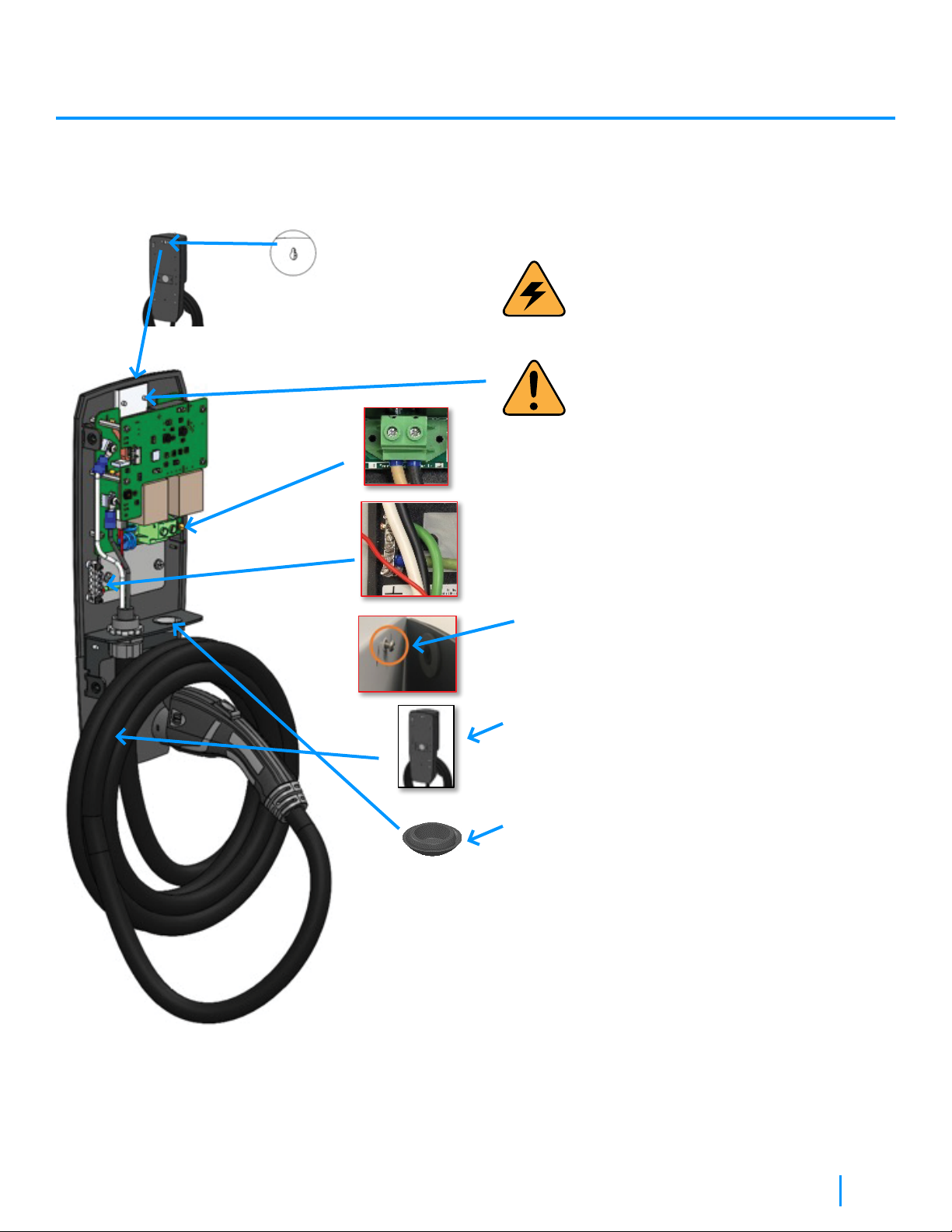
Avoid installing the EVSE in bad weather
conditions.
IMPORTANT:
the protection plate should always remain
over the keyhole.
1. Attach the head base to the wall or the post with
an anchoring apparatus that can withstand at least
56.7 Kg. (125 pound) per anchor point (2), in the
vertical and horizontal direction.
2. Hang the head base to the upper anchor
(previously fixed to the wall or post) via the keyhole
at the top. When doing so, ensure that there is a
‘tight-fit”’ such that there is not gap between the
gasket and the mounting wall.
3. Complete the mounting of the head base by
screwing a mounting bolt through the bottom
hole behind the illustrated cable, in the bottom
anchor point.
4. Remove the hole cover and attach the cable
connector to the hole from the bottom, then insert
the power cable. Make sure the conductors are
long enough to reach the terminal block.
5. Connect two power conductors (L1 and L2) and
the ground conductor (GND).
6. The grounding conductor shall be connected to
the terminal ground.
Power Cable Entry Under The Station
CoRe+ MaxTM Installation Manual

9
IMPORTANT:
the protection plate should always remain
over the keyhole.
1. Attach the head base to the wall or the post with
an anchoring apparatus that can withstand at least
56.7 Kg. (125 pound) per anchor point (2), in the
vertical and horizontal direction.
2. Hang the head base to the upper anchor
(previously fixed to the wall or post) via the keyhole
at the top. When doing so, ensure that there is a
‘tight-fit”’ such that there is not gap between the
gasket and the mounting wall.
3. Complete the mounting of the head base by
screwing a mounting bolt through the bottom
hole behind the illustrated cable, in the bottom
anchor point.
4. Remove the plate to avoid the splatter of particles
in the equipment.
5. Punch a hole of the appropriate diameter in the
plate to install the cable connector.
6. Replace the plate in place.
7. Install the cable connector to the punched hole,
then the cable. Make sure the conductors are long
enough to reach the terminal block.
8. Connect two power conductors (L1 and L2) and
the ground conductor (GND).
9. The grounding conductor shall be connected to
the terminal ground.
Power Cable Entry From The Back
CoRe+ MaxTM Installation Manual
Autres manuels pour CoRe+
5
Table des matières
Autres manuels Flo Chargeur de batteries


