fisair CCE2.0 Manuel utilisateur

FISAIR, S.L.U. C/Uranio, 20; PoI. Ind. Aimayr, 28330 San Martín de la Vega (Madrid) Spain.
Tel: (+34) 91 692 15 14 Fax: (+34) 91 691 64 56 | info@fisair.com| fisair.com
INSTALLATION AND OPERATION MANUAL
FOR THE STAGES CONTROL PANEL (CCE2.0) FOR
FISAIR EVAPORATIVE HUMIDIFIERS
Software version 2.1 | MCCE2.0-EN-21-1
In compliance with the Rules and Standards of the European Union on Machine Safety, it is essential to read this protocol
carefully before installing any equipment.

MANUAL for the Stages Control Panel | CCE2.0
2

MANUAL for the Stages Control Panel | CCE2.0
3
Contents
1. Safety instructions................................................................................................................... 5
2. General description................................................................................................................. 6
3. Operating environment............................................................................................................ 7
4. Rating plate and machine classification:.................................................................................. 9
5. Hardware description .............................................................................................................11
6. Connections...........................................................................................................................22
7. Supervision ............................................................................................................................28
8. Configuration..........................................................................................................................30
8.1. Emptying.............................................................................................................................30
8.1.1. Emptying by conductivity control: ....................................................................................30
8.1.2. Standard emptying:.........................................................................................................31
8.1.3. No emptying (never):.......................................................................................................31
8.2. Configuration Prior to Start-Up (Pre-Start-up).....................................................................32
8.3. Stages configuration:..........................................................................................................33
8.4. Conf. 0...10V or 4...20 mA: .................................................................................................34
8.5. UV lamp configuration.........................................................................................................34
8.6. Bus configuration................................................................................................................35
8.6.1. MODBUS: TCP/IP y RTU................................................................................................35
8.6.2. BACnet/IP:......................................................................................................................39
8.7. Language............................................................................................................................43
8.8. Date....................................................................................................................................43
9. Settings..................................................................................................................................44
9.1. SET-POINT µS/cm (if applicable) .......................................................................................44
9.2. TIMER T01 (ex SW1 AB)....................................................................................................44
9.3. TIMER T02 (ex SW1 CD) ...................................................................................................45
9.4. TIMER T03 (ex SW2 AB)....................................................................................................45
9.5. TIMER T04 (ex SW2 CD) ...................................................................................................45
9.6. TIMER T05 (ex SW3 AB)....................................................................................................45
9.7. TIMER T06 (ex SW3 CD) ...................................................................................................46
9.8. TIMER T07 (ex SW4 CD) ...................................................................................................46
9.9. TIMER T08.........................................................................................................................46
10. Calibration ..........................................................................................................................47
11. Launching...........................................................................................................................48
12. Alarms................................................................................................................................52

MANUAL for the Stages Control Panel | CCE2.0
4
13. Declaration of conformity....................................................................................................53
13.1. D.C. Machine...............................................................................................................53
13.2. D.C. Partly completed machinery.................................................................................54
14. Warranty.............................................................................................................................55
ANEX:
E09489-C WIRING DIAGRAM (230VAC)
E09490-C WIRING DIAGRAM (400VAC)

MANUAL for the Stages Control Panel | CCE2.0
5
1. Safety instructions
Need to consign the control panel for maintenance and revision
The machine controlled by CCE2.0 panel must not be manipulated when it is in operation.
Facing any problem that is detected in the machine during its operation, disconnect it
and set the main switch of the CCE2.0 panel using a padlock.
Installation of a residual current device in the power supply line.
The installer has to install a specific residual current device in the machine's electrical
power circuit.
FISAIR disclaims any liability if not all the installation and operating instructions it has
provided are complied with; if the products have been modified or altered without the written
consent of FISAIR; or if the products have been subjected to improper use, mishandling,
alteration, improper maintenance or show signs of negligent use or being involved in an
accident. These situations could include an incorrect power connection, impacts with other
objects, removal or disarming of security fittings/measures, etc.

MANUAL for the Stages Control Panel | CCE2.0
6
Max.25m
2. General description
The stages control panel has been specifically designed for the interconnection and supervision of
the accessories supplied with the FISAIR Evaporative Humidifiers. The incorporation of the CCE2.0
provides a more accurate, simple and reliable integration for this in air handling units.
The control panel manages all the field components of FISAIR Evaporative Humidifiers:
•Water recirculation pump
•Detector of the minimum and maximum basin water level
•Basin water supply solenoid valve
•Emptying/draining motor-valve in the basin
•Solenoid valves for different Stages
•UV lamp water treatment system (optional)
•Water conductivity control (optional)
•Modbus TCP/IP (optional)
•Modbus RTU (optional)
•BACnet/IP (optional)
* For the MAXIMUM distance of the conductivity probe, ask FISAIR when
CCE2.0 + Conductivity Control
Figure 1: Examples of installation of CCE2.0 on vertical wall and CCE2.0 integrated in the AHU
*

MANUAL for the Stages Control Panel | CCE2.0
7
3. Operating environment
The Stages Control panel is supplied in an insulating box composed of a bottom and a hinged lid
made of steel with a surface finish of RAL7035 grey weather-resistant epoxy-polyester powder with
IP54 degree of protection according to IEC-60529 and IK10 impact protection according to
IEC62262.
Operating environment temperature and humidity conditions:
•Relative humidity [5%... 95% HR], no condensation.
•Temperature [-10 °C ... +40°C]
The recommended gaps for connection, inspection and maintenance must be observed during
installation. If the box is drilled in the locations indicated for mounting, it must be ensured that a
degree of protection ≥ IP54 is maintained.
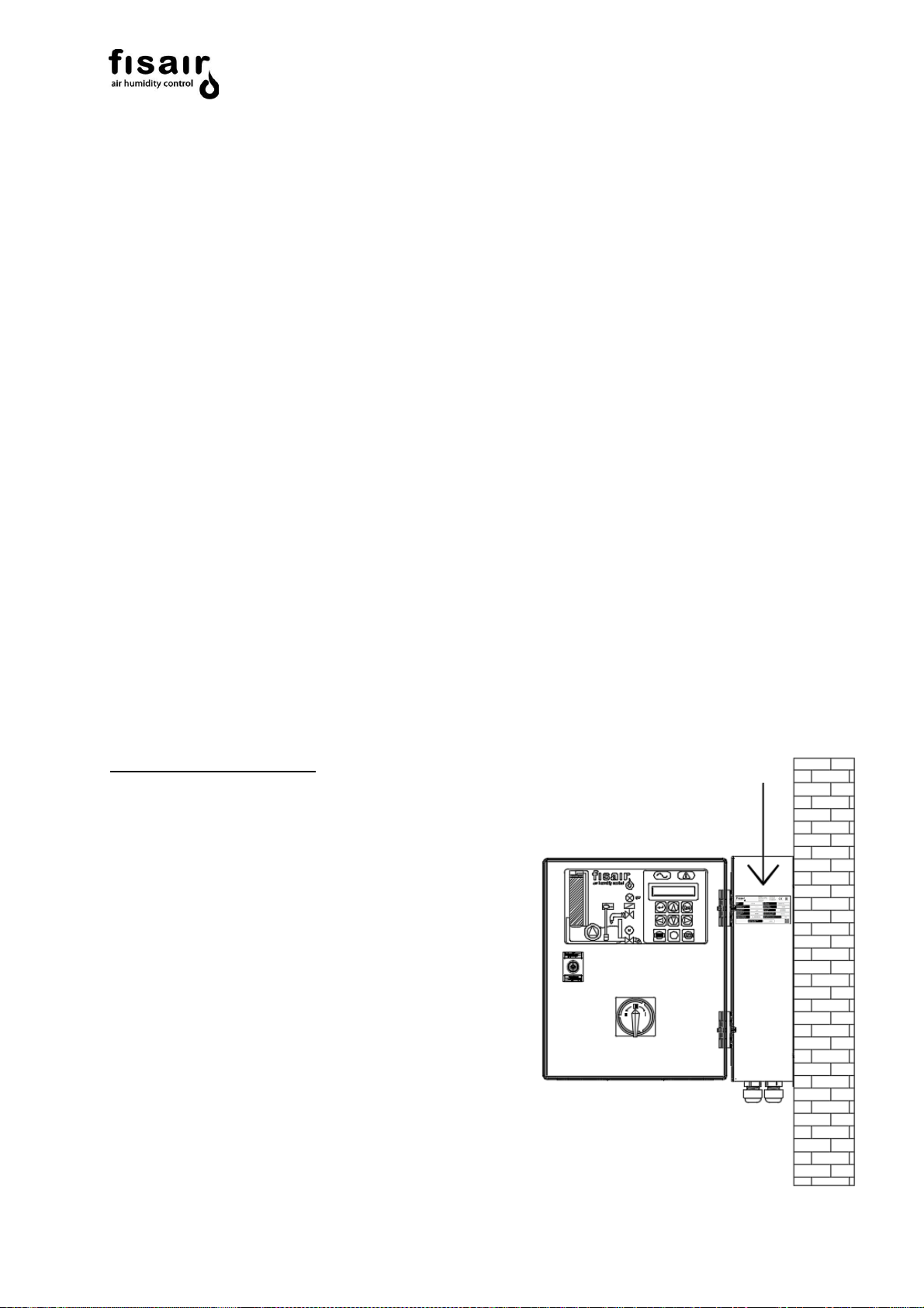
The basic control panel weighs 7,2 kg and must be installed vertically on the wall (see Figure 1) to
maintain the degree of protection IP54. Figures 2.1 and 2.2 show the minimum service spaces to be
observed and the drill hole measurements for mounting.
Figure 2.1: Vertical section: front, open door. Figure 2.2: Cross section: door closed/open
(Interior)

MANUAL for the Stages Control Panel | CCE2.0
8
INSTALLATION OF THE CONTROL PANEL OUTSIDE:
Whenever the control panel is installed outdoors, it
must be placed under an appropriate cover to protect
it from the direct incidence of rain and sun (considering
that 40ºC cannot be exceeded in the installation area):
MANUAL for the Stages Control Panel | CCE2.0
9
4. Rating plate and machine classification:
The rating plate provides essential information about the technical features of the machine.
The EC MachinerySafety Regulation requires allmachinery operated within the European Economic
Community to have a rating plate indicating its main features, the machine serial number and the
manufacturer's name inscribed in a durable manner.
According to article 2, section g of the Machinery Directive 2006/42/CE - RD 1644/2008, ‘partly
completed machinery’ means
“an assembly which is almost machinery, but which cannot in itself perform a specific application.
A drive system is partly completed machinery. Partly completed machinery is intended only to be
incorporated into or assembled with other machinery or other partly completed machinery or
equipment, thereby forming machinery to which this Directive applies”
Therefore, the CCE2.0 stages control panel is classified as a “partly completed machinery”
Nota: If the CCE2.0 stages control panel is supplied together with a device from the HEF
range, the set is classified as "machine"
Location of the rating plate:

MANUAL for the Stages Control Panel | CCE2.0
10
The rating plate shows the following information for the particular CCE2.0 stages control panel:
•Model
• Serial No.: equipment serial number
• Power supply
• Maximum power
• Rated current
• Wiring diagram
• Configuration program
• Machine type
• Designed according to the directive:
• FISAIR equipment you can join
• Year and place of manufacture.
•Service QR code and Warranty activation
Table des matières
Autres manuels fisair Panneau de contrôle


