Fass STK-5500 Manuel utilisateur
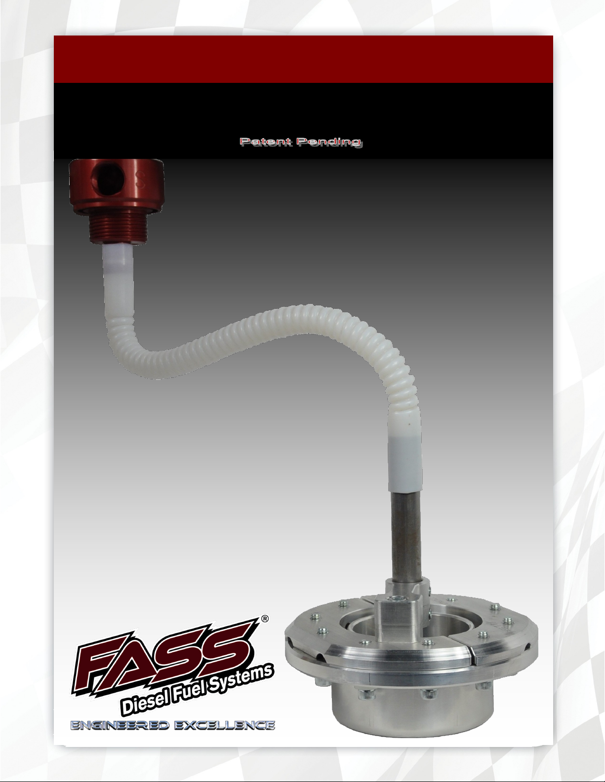
STK-5500
INSTALLATION MANUAL
ACCESSORY:
Suction Tube Kit
“SUMP”

Dear Valued Customer,
“Made in the USA” is not just a slogan at FASS; it’s what we live by! FASS is
not only assembled in the USA but 98%+ of the FASS product is manufactured in the
USA, helping to employ Americans and strengthen America. At FASS, we scrutinize
our suppliers and demand the highest quality American-made components. However,
this does come at a price, which is one of the main reasons FASS products are more
expensive than the competition. Remember price does not dictate quality but quality
does dictate price! Here at FASS, we believe it’s worth the commitment and will con-
tinue this practice to support America! Our competition is doing exactly the opposite
by using foreign-made components.
Building extremely “High-Quality” fuel products is our business. We concen-
trate all of our efforts in this arena. No one else is as specialized as FASS in what we
do! This is one of the ingredients to insure you are running with the “Highest-Quality”
fuel system in the world! We have implemented very rigorous testing procedures to
provide the “Highest Quality” we have become known for. Not only is our product su-
perior, but customer satisfaction is #1 at FASS. It is our goal to provide the best ser-
vice possible. Our confidence is evident in the products we make as each product is
backed by an industry leading warranty!
Our R & D department, in conjunction with our Dealer Support department, is
continually searching for ways to improve quality, expand our product line, and pro-
vide superb support to our network of dealers so our customers’ needs and expecta-
tions will be exceeded.
To help insure you receive the proper system and customer support at the local
level, FASS has a VIP and Authorized Dealer network representing FASS products.
We recommend you go to www.FASSride.com, click “Find A Dealer”, put in their ZIP
code, select the type of dealer, and see if the company you purchased from is listed. If
they are not, put their phone number in the field below the ZIP code field to see if they
are listed. Below these two fields is a list of “Terminated/Unauthorized” dealers. You
may want to review this list. If the company is not listed or is on the “Terminated/
Unauthorized” list, we suggest you return the product immediately to that dealer and
call FASS. We’ll recommend you to the nearest dealer.

INSTALLATION MANUAL
Follow these steps to ensure a simple installation of your new
FASS ACCESSORY
1. Read the installation manual completely before attempting installation. The instal-
lation of this product indicates that the buyer has read and understands the limita-
tions of the FASS manufacturers warranty agreement and accepts the responsibility
of its terms and conditions.
2. Inventory the package components. Notify the place of purchase immediately of
any parts missing or damaged.
3. The installation recommendations contained herein are guidelines. Use good judg-
ment and take into consideration your vehicles' accessories, i.e. empty fuel tank be-
fore beginning installation of this product.
4. For best results in accuracy and efficiency (due to training, communication, and our
relationship with our dealer network), we recommend a ViP FASS dealer for the
installation. They are prepared to install the FASS fuel pumps with the most effi-
ciency. If a situation/problem arises during the installation, they are the most pre-
pared for that situation/problem. DPPI is not responsible for any installation mis-
takes.
5. If you have any questions or concerns that can not be addressed with your dealer,
email or call FASS.
6. If any installation procedure is uncertain, contact FASS technical support.
Email [email protected] or call customer service; 636-433-5410
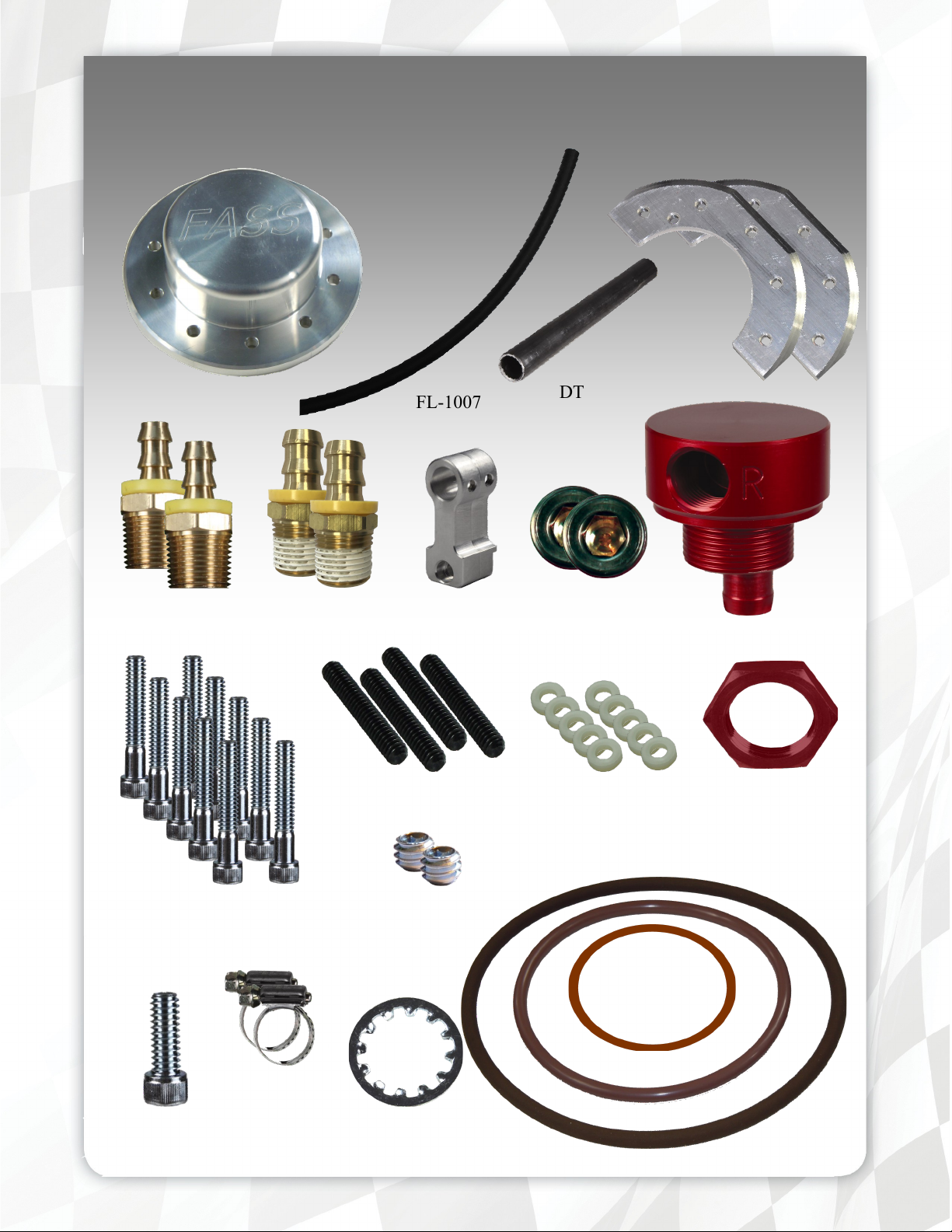
STK-5500 Contents
BHF-1002
OR-223
BHN-1001
LW-1001
1/2” Plug
DT-1002
Set Screw
SB-5500
SP-5500
OR-350Viton
OR-340Viton
SC-5500
SHCS14Z015Z (10)
1/4”-20 x 1 1/2”
PL-1001 PL-1004
Nylon Washer
11107655 (10)
SSSCP1420112 (4)
1/4-20x1 1/2
HC-1001
SHCS93164
FL-1007
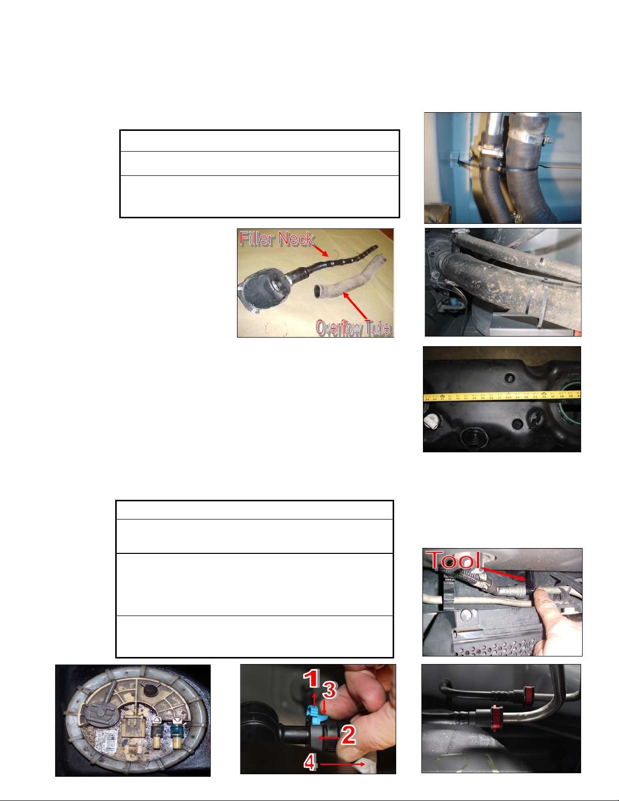
Step 1: Removing Fuel Sending Unit
Some of the photo’s are of a different application, refer to the photos that resemble your application.
Possible Variations
Clamps will be located at both ends
Clamps will be located at the tank. Some applications have an inte-
grated overflow/inner tube assembly. If so, then make sure the
inner tube does not hang-up in the tank.
C. Disconnect the factory suction and return line. If more space is required to access the top of the fuel tank,
loosen the strap nuts to the end of the stud. This will gain you about 3” more working room.
Possible Variations
Press in on the 2 blue tabs and pull off the black fuel connector.
The blue tabs will stay on the factory ports.
1. Pull up on the locking tab (either blue or yellow),
2. Push in slightly on the connector,
3. Press down on the release tab,
4. Pull the connector straight off,
Pinch in red tabs, pull out locking collar. You may have use a
Fuel Line Disconnect tool and lower the Fuel Cooler to access the
Suction line.
A. Disconnect the vehicles battery. Remove the filler neck and overflow tubes from the truck by loosening the
clamps.
B. Before tank is removed or moved, identify ALL areas of clearance be-
tween the tank and the truck’s bed for the best location to install the BHF
assembly. With proper clearance, you want to install it as close to the
Fuel sending unit as possible.
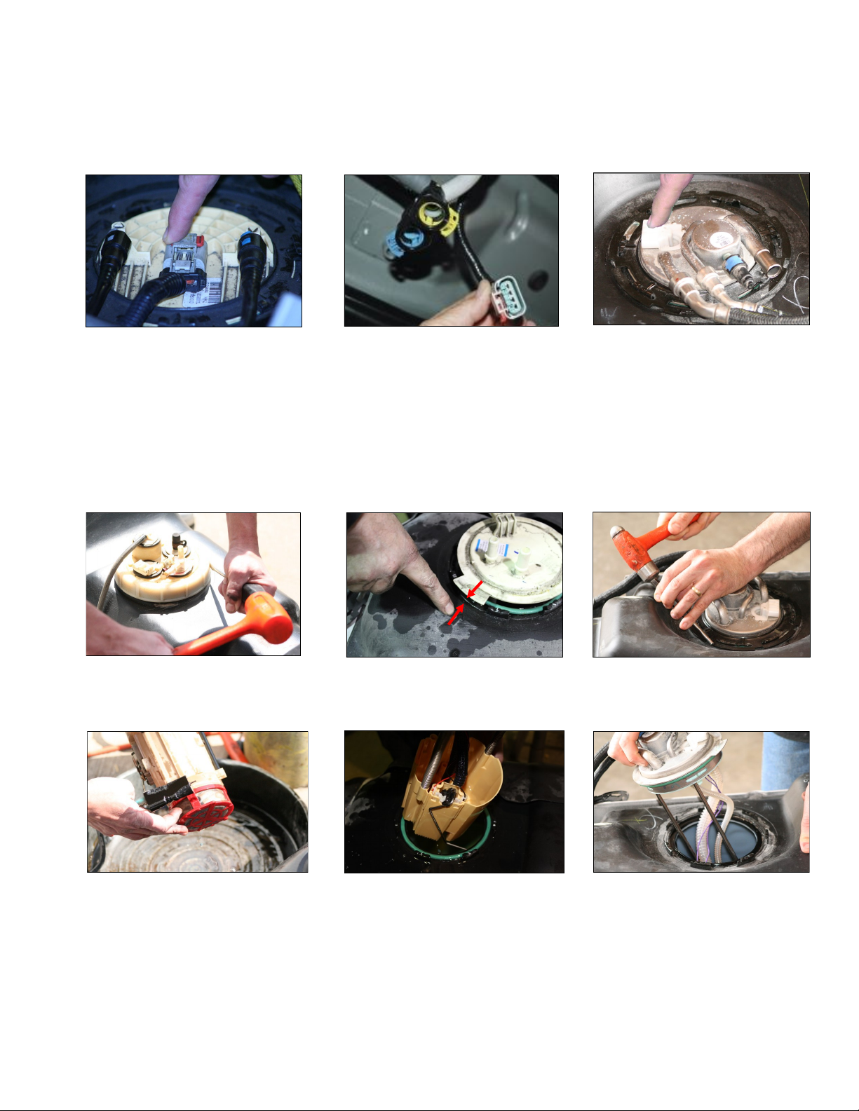
D. Disconnect the factory electrical harness.
E. Unbolt the tank and remove it from vehicle. Clean all fittings and save for reinstallation.
F. Clean the fuel module area then remove the lock ring/nut. Note/Mark the location of the fuel sending unit
in relation the top of the fuel tank fro re-installation. FORD applications will be spring loaded, hold the
unit down while removing ring to prevent it from popping up and possibly causing damage.
G. Carefully remove fuel sending unit from tank making note of the fuel level arm. Do not bend the arm.
Step 1: Removing Fuel Sending Unit
Step 2: Preparing sump
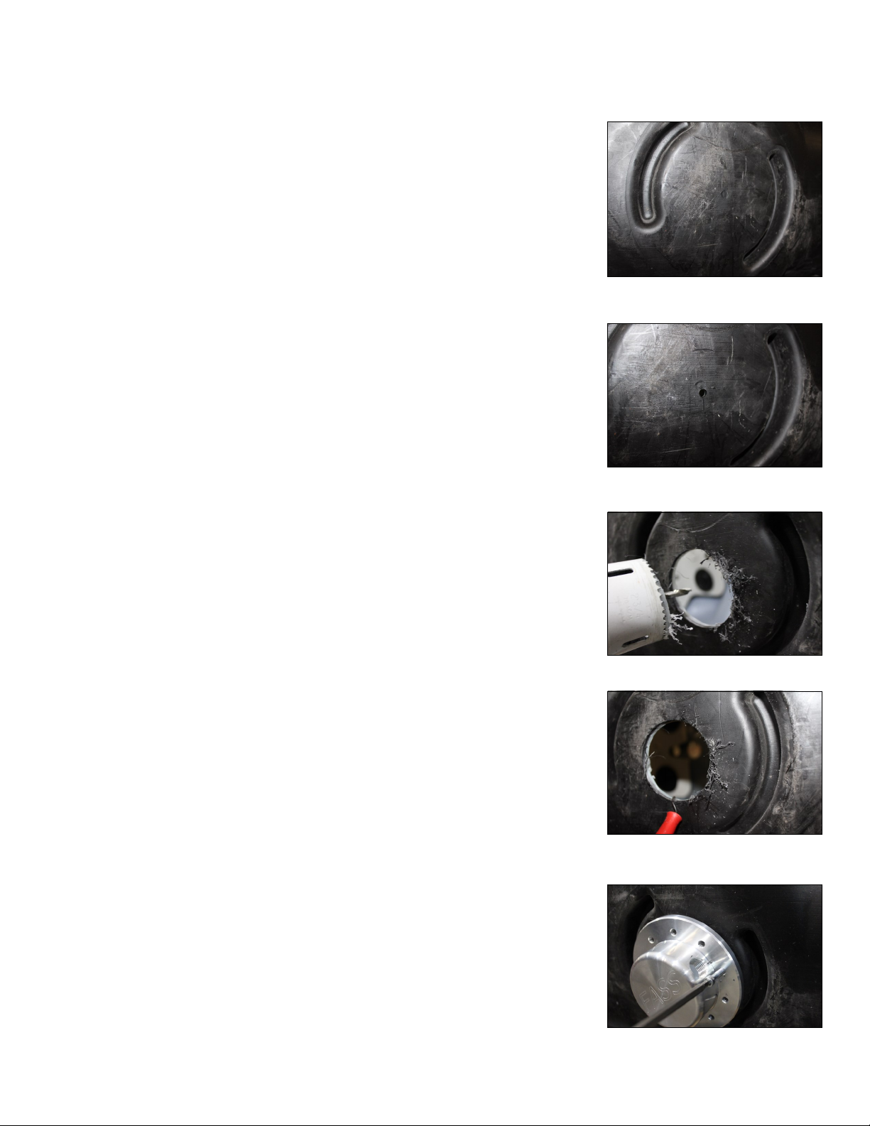
A. Locate the lowest point of the fuel tank, which is typically below the fac-
tory fuel module. On some applications there is a dimple you can use for a
center point reference and it has the flattest surface for sealing the sump.
B. Using the center point, drill a small hole to drain the remaining fuel. Rec-
ommend having a container large enough to retain the remain fuel. Allow
fuel to drain completely.
C. Drill out a 2 3/4” hole using the center point and a hole saw.
D. De-burr hole and remove all shavings.
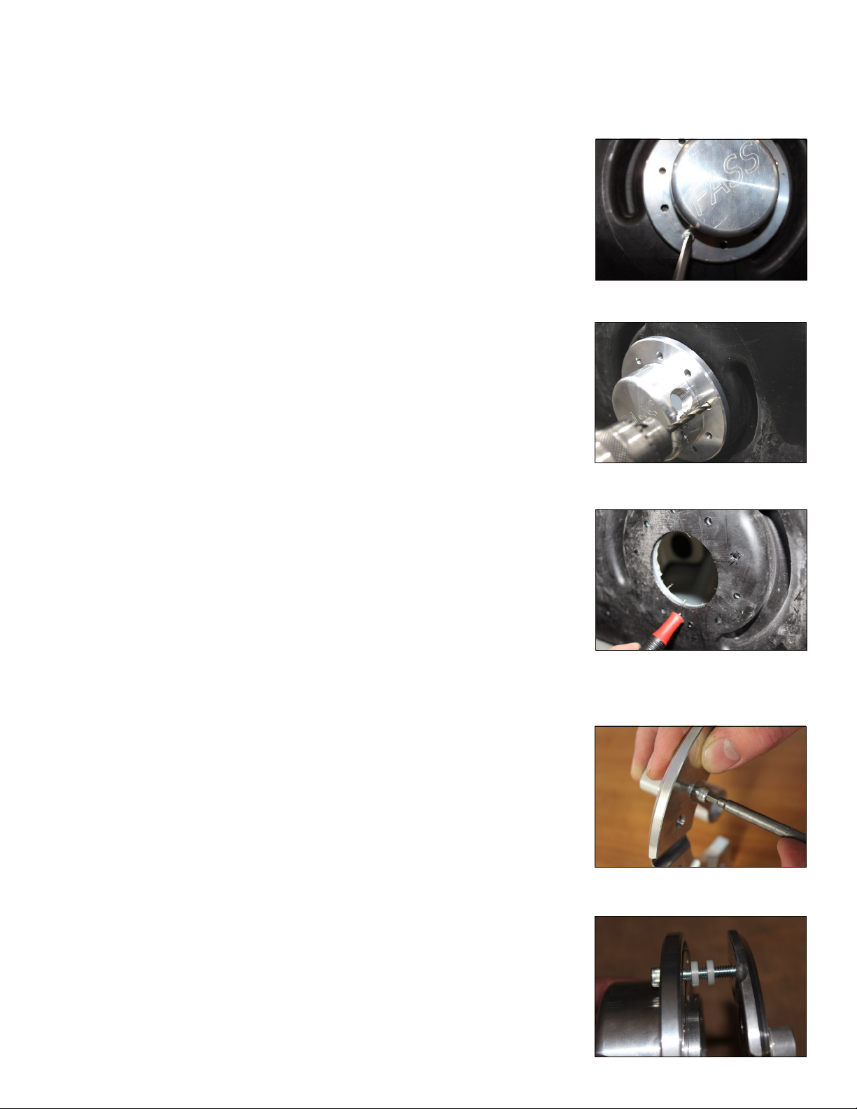
E. Place sump (SP-5500) into place, using 1 of the 10 mounting holes in the
sump drill 1 hole smaller than the 1/4” bolts. This will allow temporary
placement of 1 bolt.
Step 2: Preparing sump
F. Using a 1/4 - 20 x 1 1/2” SHCS bolt the sump into place. Opposite the
previously drilled hole drill an identical hole and insert bolt. This will
hold the sump in place to continue the next step.
G. Using the sump mounting holes as your guide, drill out the remaining 8
holes with a 1/4” drill bit. Then remove the sump and drill out the 2
smaller temporary holes (used for holding the sump) with the 1/4” drill
bit.
H. De-burr holes and remove all shavings.
I. Attach SB-5500 (sump bridge) to the SC-5500 (sump clamp).
J. Attach SC-5500 (sump clamp) to the SP-5500 (sump). Note: Stacking 2
nylon washers around the 1/4 - 20 1 1/2” SHCS should give you the thick-
ness of the fuel tank.
Preparing Sump Bridge
Step 2: Preparing sump
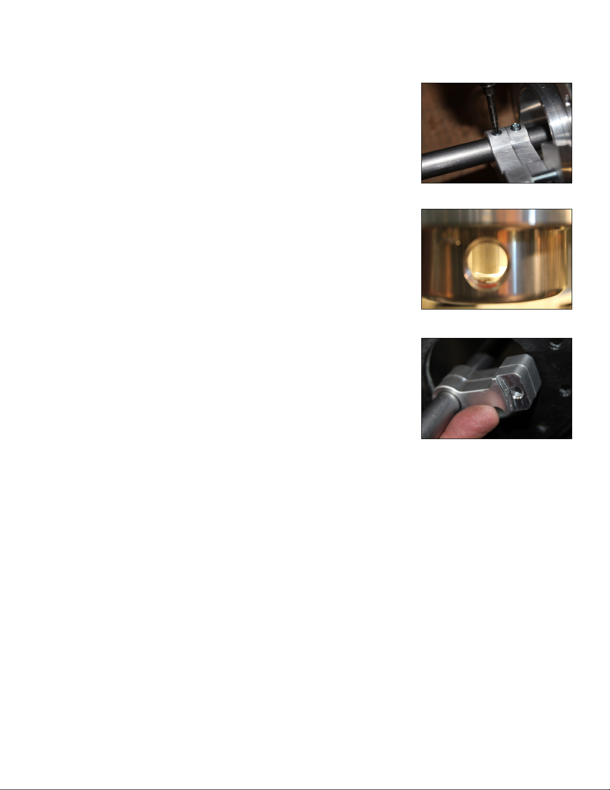
K. Install the 2 set screws into the bridge
L. Insert DT-1002 (draw tube) into the bridge. Position DT-1002 about 1/8”
to 3/16” (approximately 2 quarters) from the surface of the sump. With
the DT-1002 in proper position tighten down the 2 set screws.
M. Remove the SC-5500 (sump clamp) from the SP-5500 (sump) and then
remove the SB-5500 (sump bridge). Leaving the SB-5500 and the DT-
1002 assembled.
Step 3: Preparing Fuel Sending Unit
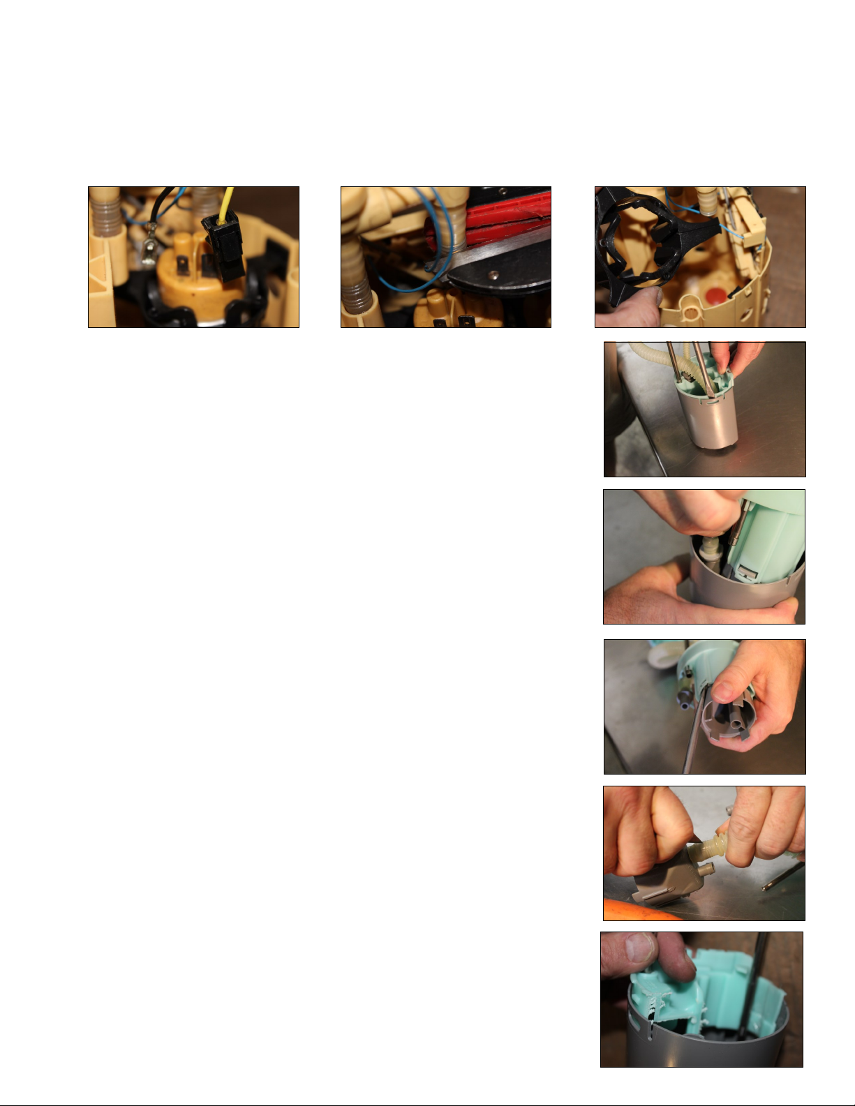
A3. Using a flat tipped screw driver, remove the suction tube footing.
A2. The factory return line nipple must be pulled or pried off the outer basket
without breaking it. The nipple will be reinstalled.
A1. If working with dual basket fuel module (some Duramax applications )
follow these subsection steps. Using a flat tipped screw driver, carefully
remove the outer basket.
A. Remove non-essential features from the center of the fuel basket.
Some of the photo’s are of a different application, refer to the photos that resemble your application.
This step is not necessary if sump is NOT going to be located below the fuel sending unit.
A4. Use a sharp blade to cut the suction tube collar and remove the plastic
footing. Discard the footing.
A5. Using tool of your choice, remove the marked area on the green inner cup.
Do not cut off the locking tab! Measure twice and cut once. When cutting
plastic use sharp tools and take your time!
Autres manuels Fass Accessoires automobiles


