Factor Electronics V-66 Manuel d'utilisation

V-66
Professional Multi-room Multi-source Audio System
User and Installation Manual

www.factorelectronics.com info@factorelectronics.com
SAFETY INST UCTIONS
RISK OF ELECTRIC SHOCK
DO NOT OPEN
IMPORTANT SAFETY INSTRUCTIONS
• Read and keep these instructions.
• Heed all warnings and follow all instructions contained within this manual.
• Do not use this unit near water.
• Clean only with dry cloth.
• Do not block any ventilation openings. Install in accordance with the manufacturer’s instructions.
• Do not install near any heat sources such as radiators heat registers stoves or other apparatus (including amplifiers) that produce
heat.
• Do not defeat the safety purpose of the polarized or grounding-type plug. A polarized plug has two blades with one wider than the
other. A grounding type plug has two blades and a third grounding prong. The wide blade or the third prong are provided for your safety. If
the provided plug does not fit into your outlet, consult an electrician for replacement of the obsolete outlet.
• Protect the power cord from being walked on or pinched particularly at plugs convenience receptacles and the point where they exit
from the apparatus.
• Only use attachments/accessories specified by the manufacturer.
• Unplug this apparatus during lightning storms or when unused for long periods of time.
• Refer all servicing to qualified service personnel. Servicing is required when the apparatus has been damaged in any way, such as when
the power-supply cord or plug is damaged, liquid has been spilled or ob ects have fallen into the apparatus, the apparatus has been
exposed to rain or moisture, does not operate normally, or has been dropped.
• Operate the product only with the voltage specified on the unit. Fire and/or electric shock may result if a higher voltage is used.
• Do not modify kink or cut the power cord. Do not place the power cord in close proximity to heaters and do not place heavy ob ects
on the power cord and/or the product itself, doing so may result in fire or electrical shock.
• Replace the protective cover over the speaker terminals after installation. Do not touch the speaker terminals as electric shock may
result.
• Ensure that the safety ground terminal is connected to a proper ground. Never connect the ground to a gas pipe, as a severe explosion
and/or fire may result.
• Be sure the installation of this product is stable avoid slanted surfaces as the product may fall and cause in ury, property damage,
electrocution and/or fire.
• Note when the unit is turned off it is not completely disconnected from the wall AC power outlet. Do not open the cover. REFER ALL
SERVICE TO A QUALIFIED SERVICE TECHNICIAN
WARNING! TO EDUCE THE ISK OF
FI E O ELECT IC SHOCK, DO NOT
EXPOSE THIS APPLIANCE TO AIN
O MOISTU E.
CAUTION! TO EDUCE THE ISK OF
SHOCK, DO NOT EMOVE THE COVE ,
NO USE SE VICABLE PA TS INSIDE.
EFE SE VICE TO A QUALIFIED
SE VICE TECHNICIAN.

www.factorelectronics.com info@factorelectronics.com
P ODUCT OVE VIEW
Thank you for choosing the Factor Electronics V-66 multi-room multi-source audio system. The V-66 provides the ultimate audio control
in six stereo zones (expandable to 18 stereo zones) without the need for programing. The V-66 is a true plug & play system while
providing an extensive list of features for professional installations the V-66 was designed to be simple to operate and easy to install.
The V-66 provides six audio inputs plus one digital optical input for Apple TV, Cable boxes, CD/DVD players and other high quality
digital audio sources. Play music from your favourite CD collection or stream wireless music directly from your smart phone,
PC or hand held music device using one of the many third party wireless internet streaming devices available today.
The V-66 can also be managed and controlled from S232 or Infrared enabled control systems completing your whole-house or
business control system. Please take the time to read this entire manual to get the most from your V-66 audio system.
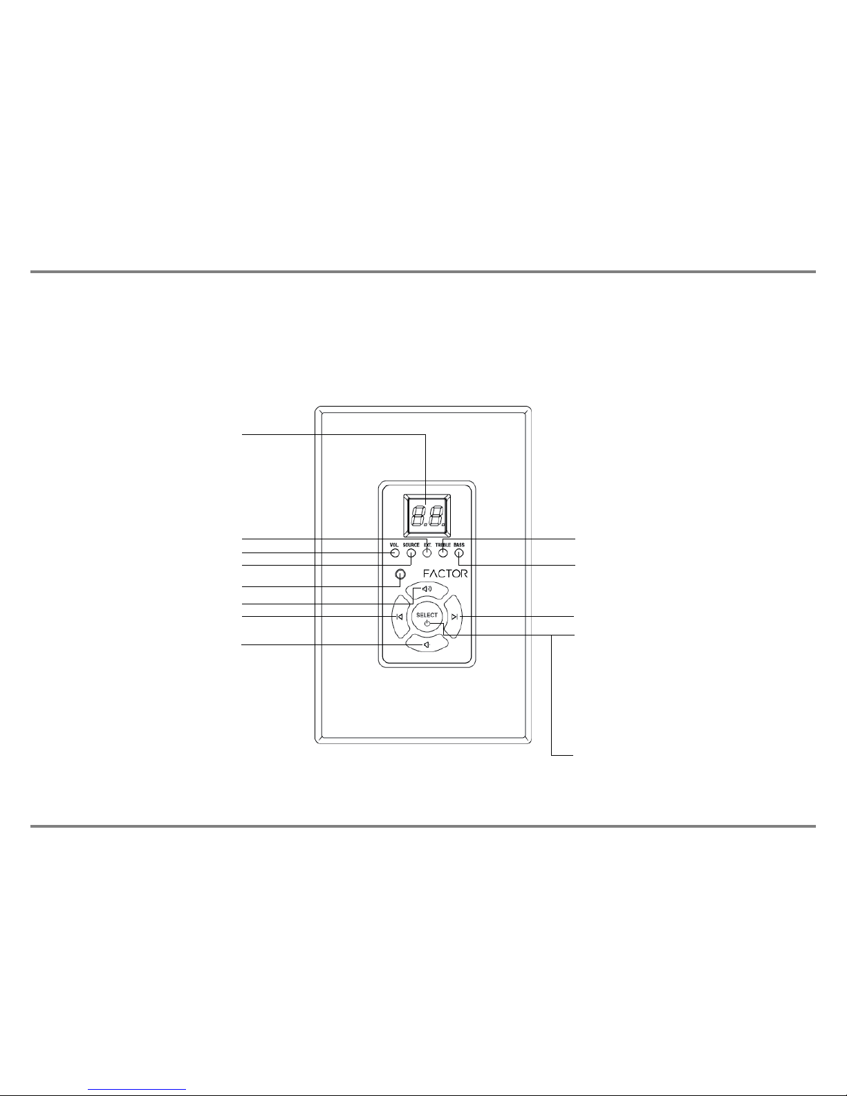
V-66 MASTE CONT OLLE /AMPLIFIE F ONT PANEL
V-66 KIT
The V-66 kit includes the following parts:
1. 1 x V-66 Master Controller/Amplifier
2. 6 x V-66 Keypad Controllers
3. 1 x V-66 Keypad In-Wall Hub Connection Plate
4. 1 x V-66 Infrared emote Controller
5. 1 x V-66 Expansion ibbon Cable
6. 1 x ack Mounting Kit
7. 1 x Installation Guide/Operation Manual
Power On/Off/ Standby
Press the power button IN to power
the system ON. All zones will be in a
standby state until a zone keypad is
enabled.
Standby/Zone ON LED
All zones will be in standby until a zone
keypad is enabled. The standby LED color
is BLUE. Once a zone keypad is enabled the
ON LED color will change to WHITE.
Peak LED
The PEAK LED is a warning light to indicate
the connected source level is too high. If the
PEAK LED lights solid ED reduce the input
or output level in the affected zone.

www.factorelectronics.com info@factorelectronics.com
V-66 MASTE CONT OLLE /AMPLIFIE EA PANEL
Stereo line level pre-amp outputs for
every zone. Connect powered sub-woofers
or high power zone amplifiers or commercial
audio amplifiers
6 x 50 watt stereo amplifiers
or 6 x100 watts in bridge mono
mode
Paging capability for Input 1
to broadcast to all zones when
12Vdc is applied to the PA - IN jack
Six stereo
analog inputs
Input 6 with Optical or analog stereo
capability for Apple TV, CD or DVD !
Expandable to 18 zones
With 3 x V-66 systems
Complete S232 control
Dual voltage
selector
115V - 230V
12 high quality amplifiers with 50 watts
output power @ 4ohms or 100 watts
@ 8ohms in bridge mono mode with
removable terminal block connectors
Zone activated 12Vdc triggers x 6
I Outputs 6 routed
& 1 common
12Vdc input
paging trigger
Mute the entire system
with the 12Vdc MUTE IN.
Use the12Vdc master output
to trigger source equipment
or home theatre equipment
Automatic gain control
protects against amp
overload
Single J45 jack
connects to the
V-66 keypad hub
for 6 keypads AC Input
115-230V
www.factorelectronics.com info@factorelectronics.com
V-66 KEYPAD FEATU ES
The V-66 keypads are available in white (V-66-WKP) and black (V-66-BKP). The V-66 keypad is designed to be very easy to use.
Five backlit buttons access zone power on/off, volume up/down, selection of sources 1-6, zone treble, zone bass, zone un-mute and
zone standby. The backlit LED display provides visual feedback of levels and source numbers. The V-66 keypad also provides an
Infrared receiver which allows complete zone control via the included V-66- C hand held remote control. The V-66 I system also sends
I commands to the V-66 master controller I output jacks for remote control of your source components. No programming necessary,
just touch the keypad and start playing music instantly!
Numeric LED Display
Volume up/down LED
Source selection LED
Ext/Mute/PA selection LED
Infrared (I ) receiver
Treble up/down LED
Bass up/down LED
Up, volume, treble, bass, un-mute
Source 1-6 descending Source 1-6 ascending
Down, volume, treble, bass, un-mute Power on/off & mode select button
Hold for 3 seconds for zone on/off
Press repeatedly for volume, source,
treble and bass adjustment mode
Use the select button with the volume
up/down buttons to adjust volume levels,
treble and bass levels
Night Light, the select button emits
a soft glow at night when the zone
is powered off

www.factorelectronics.com info@factorelectronics.com
V-66- C INF A ED EMOTE CONT OL FEATU ES
The V-66- C Infrared remote control provides complete zone control through the (I ) receiver located in the center of the V-66 keypad.
All keypad functions can be accessed with the V-66- C. In addition to this the V-66- C provides a handy MUTE button to temporarily
mute audio in the zone and left/right balance adjustment. Once the MUTE function is activated the keypad numeric LED display will flash
indicating the mute status. Press the MUTE button again to return to playing music. Pressing the volume up/down buttons on the keypad
will also un-mute the zone and return to playing music.
Zone mute
Infrared (I ) emitter
Treble up/down Bass up/down
Volume up/down
Source selection 1-6
Zone power on/off
Balance right
Balance left

www.factorelectronics.com info@factorelectronics.com
V-66 INSTALLATION INST UCTIONS
IMPORTANT: The V-66 should be situated in a well ventilated location or position. Do not block the vents on the sides or top of the
chassis. Proper ventilation is required for normal operation. Do not expose the unit to excessive dust and do not allow dust to build up
on the unit and block the vent holes in the chassis. Do not place the V-66 above or below heat-generating components such as another
audio amplifier. Be sure to leave at least 2 inches of space to the sides of the chassis with open air flow above and below the unit.
INSTALLATION:
1. The V-66 can be mounted in an equipment rack using the rack kit that is included with the V-66.
2. Always disconnect the AC power cord before making any connections to the V-66 controller.
3. Use good quality 12-14awg 2 conductor stranded copper speaker wire for all speaker connections.
4. Use good quality cat5e or cat6 cable and J45 connectors for all V-66-KP (keypads).
5. The V-66 includes a central keypad hub. All V-66-KP (keypads) will be home run back the the hub. Keep the hub close the V-66
controller.
6. Wire all cat5e/cat6 cables exactly the same using TIA/EIA 568A wiring. Do not use crossover cables.
IMPORTANT: All V-66-KP keypa s must have their mo e ip switches set properly
before powering the system on.
Failure to set the keypad mode dip switches correctly will result in no communication
between the V-66 controller and the V-66-KP (keypad). The keypad mode switches
are located on the back panel of each keypad. The dip switches set the zone location and
communication of each individual keypad.
SETTING THE KEYPAD MODE DIP SWITCHES AND KEYPAD WIRING:
Each V-66-KP shows a handy mode selection chart on the back of the keypad as follows:
Switch in the up position is ON. Switch in the down position is OFF.
IMPORTANT: Use a
screwdriver to install the
keypad. Using a power
drill can damage the
keypad.
ON
1 2 3
1 2 3
ON ON OFF
1 2 3 1 2 3
1 2 3
1 2 31 2 3
ZONE-1 ZONE-2 ZONE-3
ZONE-4 ZONE-5 ZONE-6
ON OFF ON ON OFF OFF
OFF OFF ONOFF ON OFF
OFF ON ON

www.factorelectronics.com info@factorelectronics.com
V-66-KP (keypad) INSTALLATION INST UCTIONS
IMPORTANT: The V-66-KP (keypad) should be mounted in an electrical box or in-wall mud ring using a screwdriver to tighten.
Do not use a power drill to tighten the keypad screws. Over tightening can damage the keypad.
INSTALLATION: Connecting the V-66-KP (keypa s)
Use a good quality Cat5e/6 cable and crimp J45 jacks on each end of the cables.
The J45 jack plugs into the back panel of the keypads and the 6 x J45 jacks on the back panel of the V-66-Keypad-Hub.
The V-66-Keypad-Hub is included in your V-66 kit. Plug the J45 jacks into any available jack on the V-66-Keypad-Hub.
Zone assignment is determined by the MODE dip switches on the back of the V-66-KP (keypad).
Inclu e V-66-Keypa -Hub
NOTE: Keep the hub close
to the V-66 controller
Cat5e/6
2-4 meters
Cat5e/6 200+ meters
Cat5e/6 200+ meters
Cat5e/6 200 + meters
Cat5e/6 200 + meters
Cat5e/6 200 + meters
Cat5e/6

www.factorelectronics.com info@factorelectronics.com
V-66 SPEAKE INSTALLATION INST UCTIONS STE EO MODE
IMPORTANT: The V-66 amplifiers are capable of driving 4-8 ohm speaker loads in stereo mode and 8ohm loads in bridge mono mode.
Never connect more than two 8ohm speakers wired in parallel to a single amplifier channel in stereo mode. Never connect more than one
8ohm speaker to a single channel in bridge mono mode. Never connect the Left & ight channels of the amplifier together.
Never combine the – negative channels of the amplifier together. Improper speaker installation can damage the amplifiers and void the
warranty. If you are unsure how to connect speakers to the V-66 always contact a qualified Factor Electronics technician before
connecting speakers to the amplifiers.
INSTALLATION: Connecting 8 ohm speakers to the V-66 in STEREO MODE
Use good quality 12-14awg stranded copper speaker wire. Never run speaker wires parallel to AC wires. If you must cross AC wires
always cross at a 90 degree angle. The speaker output terminal block connectors are removable. emove the terminal block connector
and make sure that all connections are open by turning each set screw counter clockwise. This insures that the speaker wire opening is
completely open. Trim approx 1/4” of insulation from the speaker wire and twist the copper ends. Insert the speaker wires into the
connector and tighten the set screws. epeat for the remaining zones.
ight Left epeat for zones 1-6
- + - +
4-8ohm speakers
Set the amplifier mode switch to STE EO

www.factorelectronics.com info@factorelectronics.com
V-66 SPEAKE INSTALLATION INST UCTIONS B IDGE MODE
IMPORTANT: The V-66 amplifiers are capable of driving 8 ohm speaker loads in in bridge mono mode. Never connect more than one
8ohm speaker to a single channel in bridge mono mode. Never combine the – negative channels of the amplifier together. Improper
speaker installation can damage the amplifiers and void the warranty. If you are unsure how to connect speakers to the V-66 always
contact a qualified Factor Electronics technician before connecting speakers to the amplifiers.
INSTALLATION: Connecting 8 ohm speakers to the V-66 in BRIDGE MODE
Setting the amplifier mode switch to B IDGE mode will double the amplifier power output to 100 watts. Effectively combining the LEFT
and IGHT amplifiers into one larger mono amplifier. The LEFT and IGHT input signals will be summed to mono. The minimum speaker
impedance in bridge mode is 8ohms. Use good quality 12-14awg stranded copper speaker wire. Never run speaker wires parallel to AC
wires. If you must cross AC wires always cross at a 90 degree angle. The speaker output terminal block connectors are removable.
emove the terminal block connector and make sure that all connections are open by turning each set screw counter clockwise.
This insures that the speaker wire opening is completely open. Trim approx 1/4” of insulation from the speaker wire and twist the copper
ends. Insert the speaker wires into the connector and tighten the set screws. epeat for the remaining zones.
MONO epeat for zones 1-6
NOTE: It is possible to set some amplifier
channels to B IDGE and some to STE EO.
Follow the correct wiring techniques and
correct speaker impedance for each zone.
- +
8ohm speaker
Set the amplifier mode switch to B IDGE
Table des matières


