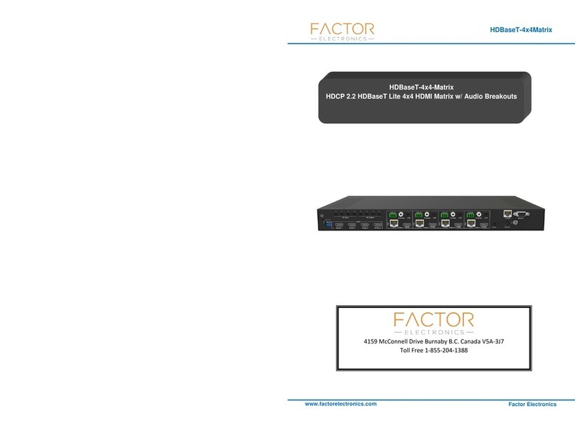
Factor Electronics HDBaseT-4x4Matrix Manuel utilisateur

1
www.factorelectronics.com
HDBaseT-4x4Matrix
Factor Electronics
4159 McConnell Drive Burnaby B.C. Canada V5A-3J7
Toll Free 1-855-204-1388
HDBaseT-4x4-Matrix(HDMI 2.0)
HDMI 2.0 18Gbps 4x4 HDMI Matrix w/ Audio Extractor

2
www.factorelectronics.com
HDBaseT-4x4Matrix
Factor Electronics
Thank you for purchasing this product. For optimum performance and safety, please read
these instructions carefully before connecting, operating or adjusting this product. Please keep
this manual for future reference.
SURGE PROTECTION DEVICE RECOMMENDED
This product contains sensitive electrical components that may be damaged by electrical
spikes, surges, electric shock, lightning strikes, etc. Use of surge protection systems is highly
recommended in order to protect and extend the life of your equipment.
SAFTY NOTICE
1. The transmission distances of HDMI over UTP cables aremeasured using TE
CONNECTIVITY 1427071-6
2. EIA/TIA-568-B termination (T568B) for CAT cables is recommended for better
performance.
3. DO NOT use 568A/568B standard mixed CAT cable (cross-over cable) because there are
2 pairs swapped, this will make POE OVER-CURRENT and damage POE components.
Please use straight-through CAT cable (both RJ45 headers are 568A or 568B standard).
4. It is recommended that power up the device after connections of source, sinkand CAT
cable.
5. To reduce the interference among the unshielded twisted pairs of wires in CAT cable, do
not run HDBaseT / Zone Cat5e/6/6a cabling with or in close parallel proximity to mains
power cables.ShieldedCAT cables can be used to improve EMI problems, which is worsen
in long transmission.
6. Because the quality of the CAT cables has the majoreffect on how long the transmission
limit can achieve and how good is the received picture quality, the actual transmission
range is subject to one’s choice of CAT cables.
7. Do not substitute or use any other Power Supply other than the enclosed unit, or a Factor
Electronicsapproved Replacement Part.Doing so will void the warranty and potentially
expose the user to dangerous voltages resulting in an electrical shock.
8. Do not disassemble the device for any reason. Doing so will void the manufacturer’s
warranty. Also, our unique case is an integral part of the design of this unit and is
responsible for cooling and circuitry shielding. Any modifications to this case will
potentially cause malfunction and product failure.
9. Do not expose the device to water, moisture, or liquids.Possible electric shock may result
as well as failure of the unit to operate.

3
www.factorelectronics.com
HDBaseT-4x4Matrix
Factor Electronics
Table of Content
Introduction.........................................................................................................................5
Features...............................................................................................................................5
Panel Descriptions..............................................................................................................6
Front Panel...................................................................................................................6
Back Panel ...................................................................................................................7
Remote Control Description ...............................................................................................8
Master Remote Control.................................................................................................8
Output and Input select.........................................................................................9
EDID Set Up.........................................................................................................9
Satellite Remote Control...............................................................................................9
Application Diagram..........................................................................................................10
Specifications....................................................................................................................10
Package Contents.............................................................................................................11
RS-232 Pin Assignment....................................................................................................11
RS232 and Telnet Commands ..........................................................................................12
GUI Control........................................................................................................................14
PC System:.................................................................................................................14
Installation..................................................................................................................14
Preparation.................................................................................................................14
Common information...................................................................................................14
“General” page............................................................................................................15
Set TCP control configuration.............................................................................16
“Port Tag” page...........................................................................................................17
Edit Input port tags .............................................................................................18
Edit Output port tags...........................................................................................18
“Setting” page .............................................................................................................19
Pop-up tag messages.........................................................................................20
Pop-up Menu......................................................................................................20
Edit selected pre-setting item..............................................................................21
“EDID control” page ....................................................................................................22
“IR Configuration” page...............................................................................................23
“FW upgrade” page.....................................................................................................24
Web GUI.............................................................................................................................25
How to enter Web GUI................................................................................................25
Admin account............................................................................................................26
Zone Page..................................................................................................................26
Status Page................................................................................................................27
Config Page................................................................................................................27
Output Page ...............................................................................................................28
Input Page..................................................................................................................28
Preset Page................................................................................................................29

4
www.factorelectronics.com
HDBaseT-4x4Matrix
Factor Electronics
EDID Page..................................................................................................................29
Audio Page.................................................................................................................30
Users Page ....................................................................................................... 30
Maintenance......................................................................................................................31
Warranty Policy.................................................................................................................31
Limitations of Warranty.....................................................................................................31
Exclusive Remedies..........................................................................................................32
RMAPolicy.........................................................................................................................32
Standard Replacement ...............................................................................................32
Once you have obtained an RMA number...................................................................33
Please note.................................................................................................................33

5
www.factorelectronics.com
HDBaseT-4x4Matrix
Factor Electronics
Introduction
The HDBASET-4X4MATRIX HDBaseT 4×4 Matrix for HDMI routes four Hi-Def sources to any
four HDTV displays, supporting 1080p Full HD up to 4K@60Hz HDR plus all 3D formats, along
with multichannel digital audio formats such as Dolby® True HD and DTS-HD® Master
Audio™. Embedded audio extractors can extract the audio and output via L/R or Coaxial.
Volume can be controlled for analogue audio out. Based on HDBaseT Lite chipset inside, the
output distance can reach up to 70m via Cat5e/Cat6. Each source can be routed to any display
using the front-panel push buttons, IR remote control, RS-232 interface, or via TCP/IP.
Features
4x HDMI inputs, 4x HDBT outputs and 1x HDMI loop output
4K@60Hz 4:4:4, HDR and full 3D
HDBT output 1 supports conversion from 4K to 1080P
1x L/R audio input, can be embedded into any HDMI input
Analogue/ digital audio output simultaneously
Push buttons, IR, RS-232, TCP/IP and Web GUI for control
EDID management
HDCP 2.2 compliant
Volume control on analogue audio outputs
12V POH

6
www.factorelectronics.com
HDBaseT-4x4Matrix
Factor Electronics
Panel Descriptions
Front Panel
1. LCD display---Shows the status of input-output selection, EDID info and so on.
2. IR receiver window----Receives the IR from the remote control of the HDBaseT-4x4Matrix.
3.Power LED indicator---Indicates the power status for the matrix.
4. Power button---Press to power on/off the matrix.
5. HDMI output selection buttons 1 to 4---Press to select the outputs from 1 to 4.
6. All button for HDMI outputs---Press to select all of the outputs from 1 to 4.
7. Menu button---Press to enter EDID set mode. Three EDID segments will display on the LCD
panel formatted as: INPUT VIDEO AUDIO, for example: IN1 1080P 2.0CH, means to set
1080P 2.0CH EDID to INPUT1. The blinking segment can be changed currently. Segment
content items listed below:
INPUT
VIDEO
AUDIO
Note
IN1
1080I
2.0CH.
IN2
1080P
5.1CH
IN3
3D
7.1CH
IN4
D1024
D1024=DVI 1024 x 768
IN5
D1080
D1080=DVI 1920 x 1080
IN6
D1200
D1200=DVI 1920 x 1200
IN7
OUT1
OUT1=Copy OUTPUT1 EDID to INPUTx
ALL
OUT2
ALL=Set EDID to ALL INPUTs
OUT2=Copy OUTPUT2 EDID to INPUTx
OUT3
OUT3=Copy OUTPUT3 EDID to INPUTx
OUT4
OUT4=Copy OUTPUT4 EDID to INPUTx

7
www.factorelectronics.com
HDBaseT-4x4Matrix
Factor Electronics
OUT5
OUT5=Copy OUTPUT5 EDID to INPUTx
OUT6
OUT6=Copy OUTPUT6 EDID to INPUTx
OUT7
OUT7=Copy OUTPUT7 EDID to INPUTx
OUT8
OUT8=Copy OUTPUT8 EDID to INPUTx
8. Up selection button--- Press to change a segment’s value.
9. ESC---Press to quit EDID set mode.
10. Lock LED indicator---Indicates the status of Lock.
11. Lock button---Press to lock the buttons of the front panel.
12. HDMI input selection button 1 to 4---Press to select the inputs from 1 to 4.
13. PTP button---Press to mirror all inputs and outputs (e.g. output 1 to input1, output 2 to
input2 and so on).
14. Selection button---Press to select a segment to change settings. The selected segment will
be blinking.
15. Down select button---Press to change segment’s value.
16. Enter button--- Press to set the EDID to a specified INPUT or copy the EDID from a
specified OUTPUT to a specified INPUT.
Back Panel
1. GND---Connect to ground if necessary.
2. IR inputs 1 to 4--- 3.5mm stereo phone-jack, connect to an IR receiver
3. IR outputs 1 to 4 --- 3.5mm mono phone-jack, connect to an IR transmitter cable.
4. RS232 port with each HDBT out--- Connect to a PC, RS232 extension to the Balun.

8
www.factorelectronics.com
HDBaseT-4x4Matrix
Factor Electronics
5. Coaxial digital audio output ---Extracted audio corresponds with the HDMI video output
6. L/R analog audio output---Extracted audio corresponds with the HDMI video output.
7. TCP/IP port –TCP/IP control
8. RS232 port –To control the matrix from a PC or control processor
9. DIP switches–Used for global EDID settings
10. HDMI inputs 1 to 4---Connect HDMI sources
11. HDBT outputs 1 to 4--- Connect via Cat6 to the remote baluns.
12. HDMI outputs 1 to4---Output to four displays, AVR etc.
13. IR extension receiver input --- 3.5mm stereo phone-jack, connects to the IR receiver cable
to receive the IR from the HDBaseT-4x4Matrix remote.
14. Power port---Use the included 24V/3.5ADC adaptor to power the matrix.
Remote Control Description
Master Remote Control

9
www.factorelectronics.com
HDBaseT-4x4Matrix
Factor Electronics
Output and Input select
A. OUTPUT-X select INPUT-Y:
1. Press OUTPUT-X (X = outputs1 to 4 )Press INPUT-Y ( Y = inputs 1 to 4 )
2. Press OUTPUT-X (X= outputs 1 to 4 )press the left and right arrow buttons to select
the input.
B. All outputs select INPUT-Y: PressALL button in zone OUTPUTPress INPUT-Y button ( Y
means 1 to 4 of inputs ), then INPUT-Y switched to ALL OUTPUTS
C. Mirror all inputs and outputs (Ex. Input 1 to output 1, input 2 to output 2, etc): Press PTP
button in the Zone OUTPUT
EDID Set Up
A. Fixed EDID to INPUT-Y/ALL
Press 1080I/1080P/3D/4KPress 2.0CH/5.1CH/7.1CHINPUT-Y/ALL button in Zone
INPUT
B. Copy EDID of OUTPUT-X to INPUT-Y/ALL
Press COPY buttonPress OUTPUT-X buttonPress INPUT-Y/ALL button
C. User defined EDID to INPUT-Y/ALL
Press USER1/USER2 buttonPress INPUT-Y/ALL
NOTE: Pressing button sequence should be finished in 5 seconds, otherwise, operation
discarded.
Satellite Remote Control

10
www.factorelectronics.com
HDBaseT-4x4Matrix
Factor Electronics
Application Diagram
Specifications
Bandwidth
18 Gbps
Video Input Connectors
4xHDMI Type A, 19-pin, female
Video Output Connectors
4xHDMI Type A, 19-pin, female, 4x RJ45 Connector
Audio Output Connectors
4x RCA(SPDIF), 4x L/R
RS232 Serial port
DB-9, female
TCP/IP Control
1x RJ45, female
IR input ports
5x3.5mm stereo jack
IR output ports
4x3.5mm stereo jack
Rack-Mountable
rack ears included
Dimensions(Lx WxD)
428mm x 235mm x 43mm, w/o feet
Shipping Weight
2.7KG
Operating Temperature
32°F to 104°F (0°C to 40°C)
Storage Temperature
-4°F to 140°F(-20°C to 60°C)
Power Supply
24V/6A DC
Table des matières
Autres manuels Factor Electronics Commutateur matriciel