FACHOWIEC KRAMER 200 Manuel utilisateur


Page 2 with 28Page 2 with 28Page 2 with 28Page 2 with 28
MANUAL - KRAMER BI-pulse MIG / MAG 200
Before using this product, read all instructions
with understanding and keep it for future use
TABLE OF CONTENTS
Safety rules, the description of symbols 3
Destiny 6
Description of the device 6
Technical data 6
Support device 7
Process MIG / MAG 9
Connecting the device to MMA 11
Description of the control panel 12
Control modes by pressing the torch 15
Storing and playback of programs from the device memory 17
System Error Codes 17
Current device support 18
Troubleshooting 20
electrical scheme 21
Ecology 21
EC declaration of conformity 23
Warranty Card 24

Page 3 with 28Page 3 with 28Page 3 with 28Page 3 with 28
MANUAL - KRAMER BI-pulse MIG / MAG 200
1. SAFETY PRECAUTIONS SYMBOLS 1. SAFETY PRECAUTIONS SYMBOLS
It is essential to read these signs and safety precautions to protect the health and life of their own and other
people.
Read instructions before starting the machine. Use only original accessories supplied by
the manufacturer.
Some components may explode. Always use face shields and protective clothing with long
sleeves.
Static electricity can damage electronic components.
Use approved face shields and welding shields. Always use protective clothing designed for
welders. Metal splinters can injure your eyes. Always use safety glasses.
Electrical shock can result in death. Do not touch electrical components when the device is
connected to the power supply. Use dry and complete protective gloves and protective clothing.
Gases and vapors can be hazardous to health. During the process of extracting welding gases
and welding fumes. Inhalation of these substances can be dangerous to your health.
Eye protection welding filters. Depending on the current intensity, use shields with appropriate
filters.
Moving parts can cause injuries unit.
Too long continuous operation may cause overheating. Wait until the device cool down.
Page 4 with 28Page 4 with 28Page 4 with 28Page 4 with 28
MANUAL - KRAMER BI-pulse MIG / MAG 200
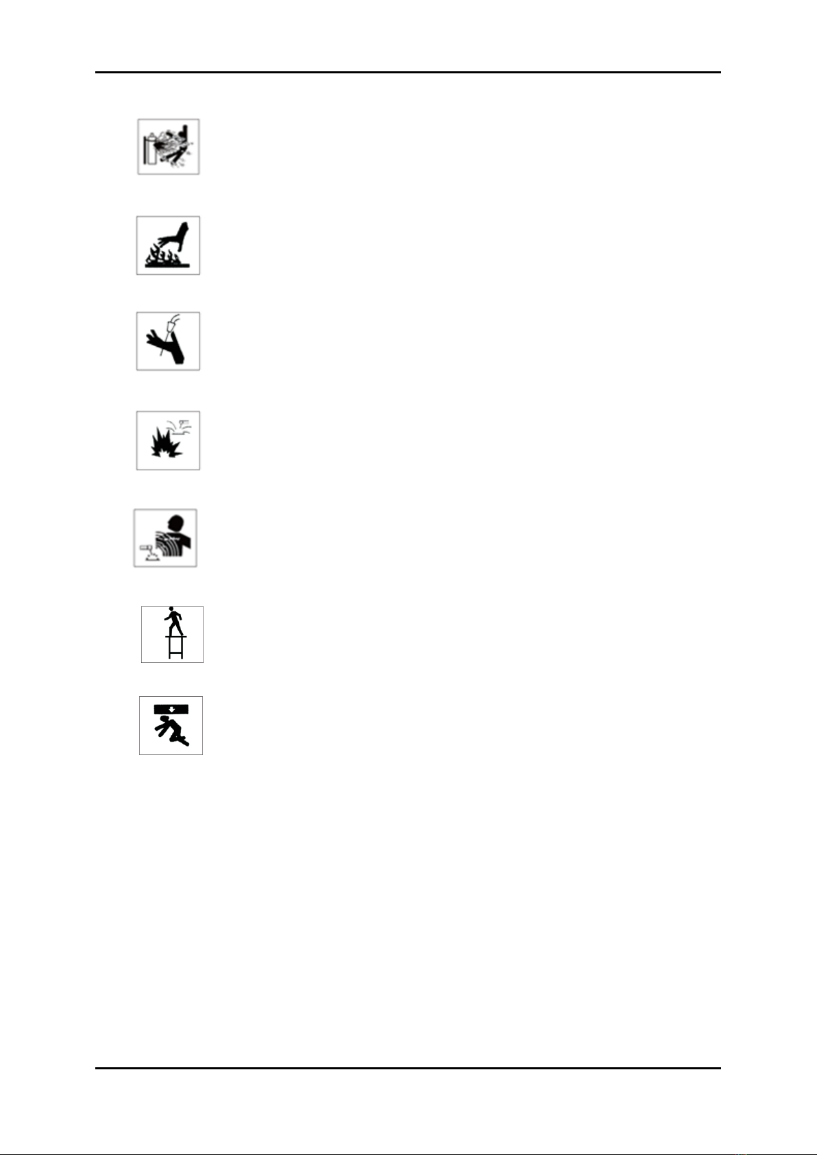
Damaged cylinders with technical gases can explode. The bottled gas is accumulated under high
pressure. Make sure the bottles are handled and stored in accordance with the requirements of
safety and fire.
Welded components could burn.
Wire protruding from the burner is sharp and can cause skin puncture.
Risk of fire and explosion. During welding work may lead to a fire. Welding station must be
separated and protected from flammable materials and explosives.
The magnetic field can disrupt the functioning of pacemakers. Before starting work, consult your
physician.
Do not weld at height without adequate protection.
Overturning or falling unit can cause serious injury.
* It is prohibited to the misuse
Welding may be carried out by qualified personnel with current training and authorization for the selected method
of welding.
ATTENTION!
Heating test was carried out at ambient temperature and the duty cycle (ratio
Load) at 40 0 C has been appointed by the simulations. Load) at 40 0 C has been appointed by the simulations. Load) at 40 0 C has been appointed by the simulations.

Page 5 with 28Page 5 with 28Page 5 with 28Page 5 with 28
MANUAL - KRAMER BI-pulse MIG / MAG 200
The device is designed to carry out welding work in professional conditions
industrial personnel holding a valid certificate of qualification compatible
with the applicable standards.
WARNING: This Class A equipment - is not intended for use
in residential locations where electricity is supplied by
system of public low-voltage network. There may be potential difficulties
in ensuring electromagnetic compatibility in those locations, due to
conducted and radiated disturbances.
The device should be used in accordance with the Regulation of the Minister of Economy of
27.04.2000r. on health and safety at work welding (Dz. U. No. 40 item.
470).
The behavior of this manual and following the guidelines set out in the
will enable proper maintenance of equipment in the future. These warnings are intended to
ensure user safety and operation in an environmentally friendly manner.
Before installation and use of the device, read carefully the contents of the entire
instructions.
•After opening the package, make sure the device has not been damaged during transport.
If in doubt, please contact our service department.
• Equipment should only use trained employee or consumer.
•During installation all activities related to electricity should
a qualified electrician.
! !

Page 6 with 28Page 6 with 28Page 6 with 28Page 6 with 28
MANUAL - KRAMER BI-pulse MIG / MAG 200
2. DESTINY 2. DESTINY
Kramer BI-pulse MIG / MAG 200 for manual arc welding GMAW (Gas Metal Arc Welding) - MIG / MAG and
MMA (Metal Manual Arc Welding).
3. DESCRIPTION OF THE DEVICE 3. DESCRIPTION OF THE DEVICE
Suitable for single-phase mains 230V, 50 / 60Hz. The device has, continuous adjustment of the welding current and is
equipped with thermal overload protection system to prevent overheating.
KRAMER BI-Pulse MIG / MAG 200 is equipped with functions synergic welding, the welding current of a single pulse,
welding and double pulse and the option electrode welding MMA.
4. TECHNICAL DATA 4. TECHNICAL DATA
Parameter KRAMER MIG / MAG PULSE BI-200
Voltage [V] 1 ~ 230
Current frequency [Hz] 50/60
Tolerance variations in the power [%] ± 10
Protection [A] 20A / 230V
Power consumption [KVA] 7.7
Load voltage [V] 58
MIG Welding current range [A] 20 - 200
Welding current range MMA [A] 20 - 150
Output voltage regulation smooth
MIG / MAG
Duty cycle MIG / MAG 60% 200A
100% 155A
The diameter of the welding wire [mm] 0.8 - 1.2
type of feeder 2R PROF.
Inductance [%] - 90 - 50
Burnback Time [%] - 90 - 90
SPOT sealing time [sec.] 0.1 - 9.9
Slow start wire [m / min] 1 - 25.5
Time intervals spot welding SPOT [s] 0.1 - 25.5
The time of gas flow before the arc ignition [s] 0 - 10
Gas flow time after the expiry of the arc [s] 0.1 - 50
Pulse frequency [Hz] 0.5 - 5.0
Pulse cycle [%] 20 - 80
Pulse modulation [%] 5 - 50

Page 7 with 28Page 7 with 28Page 7 with 28Page 7 with 28
MANUAL - KRAMER BI-pulse MIG / MAG 200
Parameter KRAMER MIG / MAG PULSE BI-200 MMA
Duty cycle MMA 60% 150A
100% 112A
The strength of the arch (Arc Force) 0-205A
Hot start (HOT START) Welding current: 0-160
Duration: 0-99ms
OTHER PARAMETERS
insulation class F
Level of security IP21S
Mass [kg] 13
Dimensions wys./szer./dł. [Mm] 360/210/470
The accessories supplied with the device:
1. Source of electricity 1. Source of electricity
2. Torch MIG / MAG 3 m Euro 2. Torch MIG / MAG 3 m Euro
3. Cable to the common terminal 3. Cable to the common terminal
4. Cable with electrode holder 4. Cable with electrode holder
5. Operating instructions in j. Polish
5. OPERATION 5. OPERATION
AND. BEFORE WORK: AND. BEFORE WORK:
• Before starting work, you must specify the place where the device is to be operated.
• Check voltage value, phase and frequency of the supply current before switching the machine to the mains.
• Parameters supply voltage are given in the section of the technical data and on the nameplate.
• Check the grounding wire connection device from the mains.
•Remove all flammable material from the welding area.
• Do not use the device on a surface, which may cause it to tip over
• Welding use suitable protective clothing: gloves, lab coat, shoes, helmet or mask having a corresponding
certificate.
B. COIL ASSEMBLY WITH welding wire B. COIL ASSEMBLY WITH welding wire
Before mounting a spool of welding wire, please refer to the data contained in the table below:
The diameter of the
welding wire
The maximum size of the reel
welding wire
The maximum recommended length
welding torch
0.8 - 1.2 mm ≤D200 - 5kg AL: STEEL 3 m 3 m

Page 8 with 28Page 8 with 28Page 8 with 28Page 8 with 28
MANUAL - KRAMER BI-pulse MIG / MAG 200
•Raise the housing cover side welding machine.
• Make sure that the roller mounted in the drive train and appropriate to the nature
wire diameter used. For steel wire, use of rolls with grooves in the shape of a "V", whereas for aluminum
wires grooved "U".
• Place the spool of welding wire spool mounting mechanism, paying attention to the direction of unwinding the
wire was in line with the direction of the entrance to the wire drive unit Lock reels from slipping by tightening
the nut on the body mounting a reel.
• End of the wire should be flat or cut off the bent section.
•In order to introduce the wire into the feeder release the pressure feed rollers.
• End of the wire inserted into the guide at the back of the tray and carry it over the driving roller introducing
nozzle of the welding gun.
•Push the wire in the groove drive roll and tighten.
•Remove the gas burner nozzles, and unscrew the contact tip.
•Switch on the device.
• Open wire welding torch so that it is simple. ATTENTION! Do not direct the tip of the welding torch in the
direction of the face or other people.
•If the gas is connected to - close the gas valve. Press the button in the handle MIG / MAG, which will result in the
development of welding wire in the holder.
•When the end of the welding wire passes through a connector in the burner, a distance of approx. 5 cm and
release the torch.
•Screw the tip and replace the current gas burner nozzles.
•Adjust the contact pressure roller by rotating the knob to the right - increase the biasing force to the left - decrease the
pressing force. Too little downforce, will cause slippage of the drive roller. Too high pressure causes an increase in
resistance of administration and the deformation of the wire.
Figure 1. The direction of rotation of the reel of welding wire (illustrative photo)
C. INSTALLATION shielding gas bottle
• Connect with semiautomatic bottle with a suitable cable.
• Unscrew the regulator valve prior to welding.
•After completion of welding, always turn off the valve on the cylinder.

Page 9 with 28Page 9 with 28Page 9 with 28Page 9 with 28
MANUAL - KRAMER BI-pulse MIG / MAG 200
Scheme connect the device in the MIG / MAG welding.
ATTENTION !
In operating mode MIG / MAG welding wire closing circuit located on the front of the device must always be
connected to the positive polarity "+".
6. WELDING PROCESS MIG / MAG 6. WELDING PROCESS MIG / MAG
Arc welding shielding gases (indicated by MIG / MAG) is one of the most widely used process for producing weldments.
Abbreviation MAG (metal active gas) includes in its description of the active shielding gases. Abbreviation MIG (Metal
Inert Gas), refers to inert gas shroud. Semi-automatic welding process involves melting the edge of the work piece and
the material of the consumable electrode arc heat glowing between the electrode in the form of a solid wire and the
welded workpiece, in inert gas or active. Primary shielding gases for welding MIG inert gases such as argon, helium,
and gases

Page 10 with 28Page 10 with 28Page 10 with 28Page 10 with 28
MANUAL - KRAMER BI-pulse MIG / MAG 200
active in the MAG CO 2 H 2 ABOUT 2 N 2 and NO, for the addition to argon or helium. The consumable electrode is in the active in the MAG CO 2 H 2 ABOUT 2 N 2 and NO, for the addition to argon or helium. The consumable electrode is in the active in the MAG CO 2 H 2 ABOUT 2 N 2 and NO, for the addition to argon or helium. The consumable electrode is in the active in the MAG CO 2 H 2 ABOUT 2 N 2 and NO, for the addition to argon or helium. The consumable electrode is in the active in the MAG CO 2 H 2 ABOUT 2 N 2 and NO, for the addition to argon or helium. The consumable electrode is in the active in the MAG CO 2 H 2 ABOUT 2 N 2 and NO, for the addition to argon or helium. The consumable electrode is in the active in the MAG CO 2 H 2 ABOUT 2 N 2 and NO, for the addition to argon or helium. The consumable electrode is in the active in the MAG CO 2 H 2 ABOUT 2 N 2 and NO, for the addition to argon or helium. The consumable electrode is in the active in the MAG CO 2 H 2 ABOUT 2 N 2 and NO, for the addition to argon or helium. The consumable electrode is in the
form of the solid wire, typically having a diameter of 0.6 to 1.2 mm and is fed continuously by a special supply system,
a speed of 2.5 m / min and above. The welding may be water-cooled or gas shielding. Welding is carried out mainly
constant current of positive polarity as a semi-automatic welding, mechanized, automated or robotic using specialized
equipment. Glowing shield arc between the consumable electrode and the weld material for forming the weld in a very
favorable thermal and chemical conditions. Welding of this type can be used to make high quality of the connections of
all the metals which may be joined by arc welding. Belong to them: carbon steels and low alloy steels and corrosion
resistant. Welding can be carried out in the workshop and field in all positions.
Figure 2. MIG / MAG - scheme
Brazing MIG / MAG
Braze welding method of joining materials, a combination of two processes: brazing and MIG / MAG welding.
Similarly as during the soldering process braze there is no building-up edges of the metal. The preparation of the
material, the method of wire feed gas to protect the weld pool (usually pure argon) - are the hallmarks of which are
characteristic of the MIG / MAG welding. As additional material is most commonly used wire CuSi (CuSi3) elements
galvanized steel wire or SG-CuAl elements of aluzinc or aluminum.
Table des matières
Autres manuels FACHOWIEC Système de soudage


Manuels Système de soudage populaires d'autres marques


TAFA
TAFA 30*8B35 Manuel utilisateur

Lincoln Electric
Lincoln Electric INVERTEC V350-PRO CE Manuel utilisateur

ESAB
ESAB Buddy Arc 145 Manuel utilisateur

CIGWELD
CIGWELD 636804 Guide rapide

Red-D-Arc
Red-D-Arc DC-400 Manuel utilisateur

Hobart Welding Products
Hobart Welding Products Spool Gun DP 3035-10 Manuel utilisateur


