EXXOTEST MX100 Manuel utilisateur

Document n° 00305023-v1
VEHICLE TESTER EXXOTEST MX100
For testing lines and voltage drops (12V)
User’ guide
1
7 8
2
6
3
5
4
10 9

WARNING AND GENERAL PRECAUTIONS
READ BEFORE USING THE MX100
To ensure that the MX100 is used in safe conditions and to avoid damaging
the device:
Only use the MX100 in compliance with the provisions of this manual
to avoid hampering its built-in protection devices.
Do not use the MX100 if the device or its measuring leads are
damaged, or if the device does not appear to be operating correctly.
Check the operation of the MX100 by measuring a direct voltage. If in
doubt, ensure the device is checked.
Never apply voltage in excess of 30V.
Do not use the device near to explosive gases, vapour or dust.
Comply with all safety instructions for the equipment being tested.
!

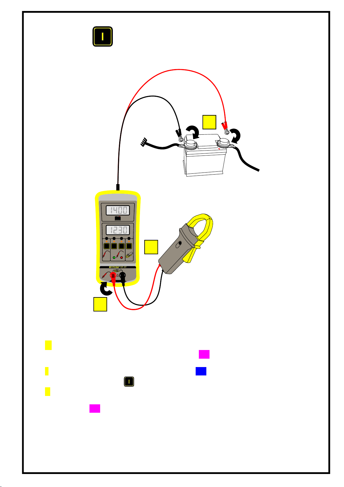
VOLTMETER MODE
Carry out the following operations:
1 Connect the power clamps on the device to the battery terminals, the device will turn on and
indicate the battery voltage on the display 111
2 Switch the device to Voltmeter mode by pressing 555
(This mode is selected by default when starting the device)
3 Take measurements using the test lead, with the device connected to the vehicle earth, and using
this lead alone. The result will appear on the display 222
+
-
1mv/A
UU IT
V V A
+
-V
-
1
3
2

+
-
1mv/A
UU IT
V V A
+
-V
-
DIFFERENTIAL VOLTMETER MODE
Carry out the following operations:
1 Connect the power clamps on the device to the battery terminals, the device will turn on and
indicate the battery voltage on the display 111
2 Switch the device to Differential voltmeter mode by pressing 535
3 Take measurements using the test lead, the device will automatically display the voltage
difference between the point measured and the reference value. This difference may be positive
or negative:
Green LED on: measurement with reference to the battery earth
Red LED on: measurement with reference to the battery + terminal
7
8
1
3
2
IMPORTANT
MEASUREMENTS ARE ALWAYS TAKEN WITH REFERENCE TO A REFERENCE VOLTAGE
(BATTERY EARTH OR + TERMINAL)
+
-
1mv/A
UU IT
V V A
+
-V
-
MODE AMPEREMETRE
1 Connect the power clamps on the device to the battery terminals, the device will turn
on and indicate the battery voltage on the display 111
2 Switch the device to Ammeter mode by pressing 565
3 Take measurements using an ammeter clamp (not supplied), check that the clamp is
on and at the appropriate rating (refer to the manufacturer manual), read the result on
the display 222.
1
3
2

+
-
1mv/A
UU IT
V V A
+
-V
-
AUTOMATIC TEST LINE MODE
This mode can be used to locate an unsatisfactory connection. This mode is used if a difference in
potential is detected between one of the battery terminals and a point which should be connected. In
this case, the device calculates the resistance between the point measured and the reference
(battery).
Carry out the following operations:
1 Connect the power clamps on the device to the battery terminals, the device will turn on and
indicate the battery voltage on the display 111
2 Switch the device to Automatic test line by pressing 545
3 Take measurements using the test lead, the result will appear on the display 222.
The device automatically displays the value of the resistance between the measuring points
and one of the battery terminals, one of the LEDs ( or ) will light up to indicate if the
point measured is closer to the + terminal or the earth of the battery.
7
8
IMPORTANT
MEASUREMENTS SHOULD BE TAKEN ON A DE-ENERGISED LINE (NO LOAD)
1
3
2
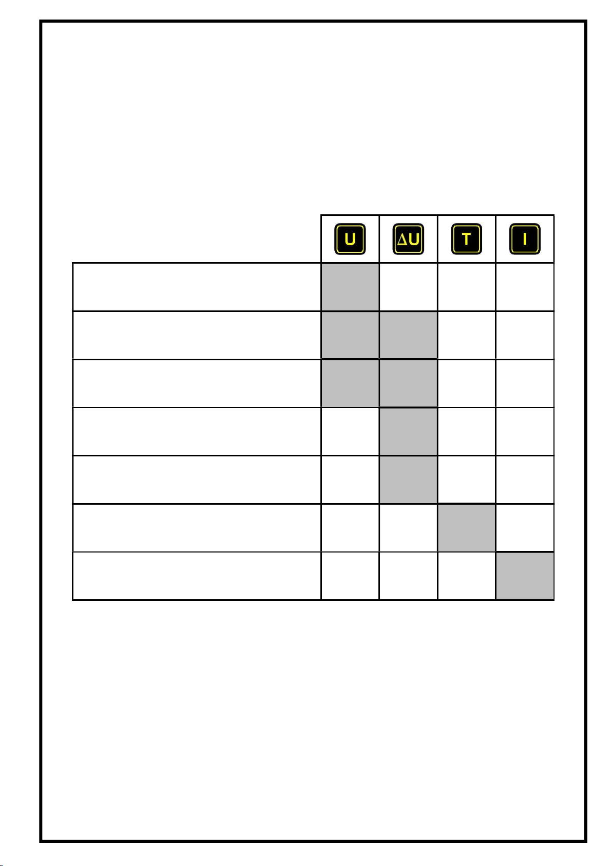
WHICH MODE SHOULD BE USED?
Here are a few examples of measurements taken with the EXXOTEST MX100:
Measuring a probe voltage
Measuring a supply voltage
Measuring an "earth"
Measuring a voltage drop triggered by a
unsatisfactory contact
Measuring the quality of a battery earth or +
terminal
Measuring the resistance of a line*
Measuring an intensity using an ammeter
clamp
*after having detected a voltage drop in Differential Voltmeter mode (∆U).

INTERPRETING POLARITY LEDS
INDICATIONS FOR MEASURING POLARITY
FOR AND MODES.
Voltage measured using the test lead:
If the red LED is on:
Measurements are taken with reference to the battery plus terminal.
If the green LED is on:
Measurements are taken with reference to the battery earth.
8
7
100% of battery voltage
0% of battery voltage
50% of battery voltage
+
-
1mv/A
7 8

0,1
V0,2 0,3 0,4 0,5 V/Volts
1 2 3
1
10
I/ Ampère
20
5
2
30
5
4
Pertes en Puissance
10 15 20 25 30 40 50 %5
R = 0,1
R = 0,2
R = 0,5
R = 1
Chute de tension
Courant
CHARTS FOR RATIOS BETWEEN VOLTAGE, CURRENT,
LINE RESISTENCE AND POWER OUTPUT
Pertes en puissance Power losses
Courant Current
Chute de tension Voltage drop
Volts Volts

Example:
With a 14V battery, a voltage drop of 1V corresponds to a 15% loss in power.
i.e. R=0.2Ω to 5A or R=0.1Ω to 10A
CHARACTERISTICS
These technical characteristics imply:
a one-year calibration cycle
an operating temperature of 2 - 40°C
a maximum humidity level of 80%
a power supply between +10 and +15 V
Function Measuring
span Resolution
Precision
+/- (% display) +
(digits)
Comments
Battery Voltmeter
19.99V 0.01V 0.2% +/-1 Input impedance = 750kΩ
DC Voltmeter 19.99V 0.01V 0.4% +/-2 Input impedance = 150kΩ
Differential
voltmeter 19.99V 0.01V 0.4% +/-2
Input impedance = 150kΩ
Display "---" if the
measurement is out-of-
tolerance
Line resistance
measurement 19.99Ω 0.01Ω 3% +/-50mΩ
Measuring current 0.1A
Max. voltage = battery
voltage
Ammeter with
AC/DC clamp
1mV/A or
10mV/A
+/-2V
1999 A or
199.9 A
1mV
1A
0.1A
0.2% +/- 2
(+ clamp error)
Measurement +/- 2V DC
Input impedance = 500kΩ
Table des matières
Manuels Équipement de test populaires d'autres marques

SMART
SMART KANAAD SBT XTREME 3G Series Manuel utilisateur

Agilent Technologies
Agilent Technologies BERT Serial Manuel utilisateur

Agilent Technologies
Agilent Technologies N3280A Manuel utilisateur

Vernier
Vernier Go Direct Voltage Manuel utilisateur

Lifeloc
Lifeloc R.A.D.A.R. Manuel utilisateur

Fluke
Fluke T5-600 Instructions d'utilisation et d'installation


