Extra HDP-MXB42AP Manuel utilisateur

4×2 HDMI 2.0 18Gbps Matrix Switcher
VER 1.0

Thank you for purchasing this product
For optimum performance and safety, please read these instructions carefully
before connecting, operating or adjusting this product. Please keep this
manual for future reference.
Surge protection device recommended
This product contains sensitive electrical components that may be damaged
by electrical spikes, surges, electric shock, lighting strikes, etc. Use of surge
protection systems is highly recommended in order to protect and extend the
life of your equipment.
Table of Contents
1. Introduction...........................................................................................
2. Features.................................................................................................
3. Package Contents...............................................................................
4. Specifications.......................................................................................
5. Operation Controls and Functions......................................................
5.1. Front Panel...................................................................................
5.2. Rear Panel....................................................................................
5.3. Connecting to the Matrix............................................................
5.4. Using the Matrix............................................................................
5.5. IR Pin Definition.............................................................................
6. IR Remote..............................................................................................
7. Using the Built-In Web Interface..........................................................
8. ASCII control command......................................................................
9. Application Example............................................................................
1
1
1
2
3
3
4
5
6
7
8
9
18
24

1. Introduction
2. Features
☆HDMI 2.0, HDCP 2.2 / HDCP 1.4 and DVI 1.0 compliant
☆Four 18G HDMI 2.0 video inputs supporting up to 4K60 444 resolution
☆Two 18G HDMI 2.0 video outputs supporting up to 4K60 444 resolution
☆Both outputs can be individually scaled for 4K→1080p or HDBaseT mode
☆Automatic RS232, CEC and IR control of the display device power state
☆Two sets of de-embedded audio analogue and TosLink outputs, for both
outputs
☆ARC decoding to the TosLink audio outputs only
☆Test Pattern mode for testing output signal integrity to the display
☆Built-in Web GUI for LAN control
☆Four methods of control: Front panel, RS232, IR and LAN
3. Package Contents
1 / 24
This product is an 18G HDMI video switcher with 4 HDMI inputs and 2 scaling
HDMI outputs. Each input and output supports up to 4K60 444 HDMI 18G
video. The outputs can be individually scaled for 1080p or HDBaseT
compatibility. De-embedded audio as analogue L+R and optical TosLink is
available for both outputs. The Matrix Switcher can automatically control the
display device using RS232, CEC or IR when the last input signal is lost, or
when the first video input is detected. This switcher can be controlled from
the front panel, RS232, IR, or LAN.
Qty Item
4×2 HDMI 2.0 18Gbps Matrix Switcher
12V/1A Locking Power Adapter
IR Remote
Mounting Ears
IR Blaster Cables (1.5 meters)
20~60KHz IR Receiver Cable (1.5 meters)
3-pin Phoenix Connectors
User Manual
1
1
1
2
2
1
5
1

4. Specifications
Technical
HDMI Compliance HDMI 2.0
HDCP Compliance HDCP 2.2 and HDCP 1.4
Video Resolution
4K2K 50/60Hz 4:4:4
4K2K 50/60Hz 4:2:0
4K2K 30Hz 4:4:4
1080p, 1080i, 720p, 720i, 480p, 480i
All HDMI 3D TV formats
All PC resolutions including 1920 x 1200
Color Space RGB, YCbCr4:4:4, YCbCr4:2:2, YCbCr 4:2:0
Color Depth 8-bit, 10-bit, 12-bit [1080P, 4K30Hz, 4K60Hz (YCbCr 4:2:0)]
8-bit [4K60Hz (YCbCr4:4:4)]
HDMI Audio Formats
PCM2.0/5.1/7.1CH, Dolby Digital/Plus/EX, Dolby True HD,
DTS, DTS-EX,DTS-96/24, DTS High Res, DTS-HD Master
Audio, DSD
Optical Audio Formats PCM2.0, Dolby Digital / Plus, DTS
L/R Audio Formats PCM2.0CH
(Note: If ARC function is turned on, the audio port will mute.)
ESD Protection Human-body Model: ±8kV (Air-gap discharge),
±4kV (Contact discharge)
Video Bandwidth
18 Gbps
HDR formats HDR10, HDR10+, Dolby Vision, HLG
Output Scaling 4K to 1080p
4K to HDBaseT (Down-scale to no more than 10.2Gbps)
3D Support Yes
Audio Frequency
Response 20Hz to 20kHz, ±3dB
RS232 Control 57600, No parity, 8 data bits, 1 stop bit, No handshaking
RS232-A and
RS232-B
Configurable from 4800 to 115200 baud; 7 or 8 bits; none,
odd or even parity and 1 or 2 stop bits.
2 / 24

Resolution / Cable
length
1050g
Input: AC100~240V 50/60Hz
Output: DC12V/1A (Locking connector)
4.3W (max)
0°C ~ 40°C / 32°F ~ 104°F
-20°C ~ 60°C / -4°F ~ 140°F
Power Supply
Dimensions
Weight
Metal Enclosure
Operating
Temperature
Storage Temperature
Relative Humidity 20~90% RH (non-condensing)
Power Consumption
Color Black
218mm(W)×140mm(D)×43mm(H)
Housing
Mechanical
4K60 -
Feet / Meters
4K30 -
Feet / Meters
HDMI IN / OUT 32ft / 10M16ft / 5M
The use of “Premium High Speed HDMI” cable is highly recommended.
1080P60 -
Feet / Meters
50ft / 15M
Connections
Input Ports 4×HDMI Type A [19-pin female]
Output Ports
2×HDMI Type A [19-pin female]
2×L/R audio out [3-pin phoenix connector]
2×OPTICAL audio out [S/PDIF]
2×RS232 A/B [3-pin phoenix connector]
Control port
1×LAN [RJ45]
3×RS232 [3-pin phoenix connector]
1×IR IN [3.5mm Stereo Mini-jack]
2×IR OUT A/B [3.5mm Stereo Mini-jack]
3 / 24
Out A / Out B
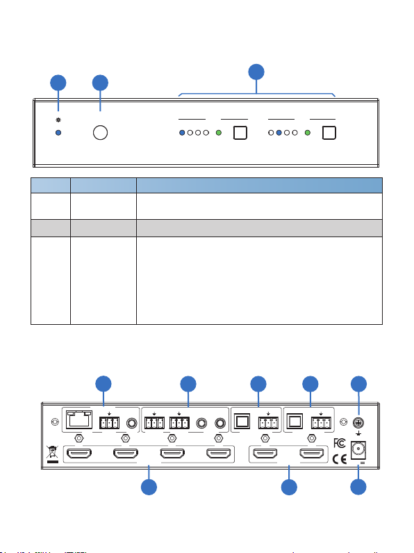
5.2 Rear Panel
Tx Rx Tx Rx Tx Rx RL RL
OPTICAL OPTICAL
AUDIO OUT AAUDIO OUT B
A B
12V
IR IN
RS232
LAN
BA4321
SOURCE
CONTROL
DISPLAY
RS232-A RS232-B IR OUT
45 6 78
123
5. Operation Controls and Functions
5.1 Front Panel
Number Function descriptionName
1 Power LED Blue LED indicates that the unit is powered.
Red LED indicates that the unit is in standby mode.
Out A Out B
1 2 3 4 Auto1 2 3 4 Auto
IR
18Gbps HDMI 4x2 Matrix
1 2
3
2 IR Sensor IR input for remote control of the switcher
3
LED and button for each output
■ LED 1 to LED 4: Blue LED Indicates when the input is
selected for the respective output.
■ Auto LED: Green when Auto detection mode is enabled.
▪ Press to select the desired input.
▪ Press and hold for 3 seconds to toggle the Auto
detection mode.
4 / 24

CONTROL
SOURCE HDMI Source inputs 1 to 4
DISPLAY HDMI outputs for displays A and B.
12V Plug DC 12V/1A power supply into the unit and connect
the adapter to an AC outlet.
Number Function descriptionName
1
2
3
4
LAN (RJ45): Control port for LAN control or accessing
the built-in Web GUI.
RS232: 3-pin pluggable connector for RS232 control of
the Matrix.
IR IN: IR Eye input for IR control of the Matrix.
5
RS232-A /
RS232-B
3-pin pluggable connectors for RS232 of the display
devices.
IR OUT A /
IR OUT B IR eye output for IR control of the display devices.
6AUDIO OUT A
TosLink connector for optical audio from HDMI Output A
3-pin pluggable connector for stereo audio from HDMI
Output A
7 AUDIO OUT B
TosLink connector for optical audio from HDMI Output B.
3-pin pluggable connector for stereo audio from HDMI
Output B.
8 Earthing Point Screw terminal for earthing the Matrix.
1. Connect the desired HDMI input sources.
2. Connect the desired HDMI display devices.
3. Connect any CONTROL inputs that may be required: LAN, RS232, or IR IN.
4. Connect any Display control port: RS232-A, RS232-B, IR OUT A or IR
OUT B.
5. Connect any audio devices to either the Optical or L+R outputs.
6. Connect the 12V DC PSU.
5.3 Connecting to the Matrix
5 / 24

5.4 Using the Matrix
The Power LED provides the following indications:
Colour Description
Blue The Matrix is active and fully controllable
Red
The Matrix is in standby mode, this state can be
changed by using RS232 or LAN commands, or from
the Web GUI interface.
5.4.2 Auto LED and Button
5.4.1 Power LED and Standby Mode
The green AUTO LED for both outputs A and B is lit when that channel has
its Auto Detection mode active. Auto Detection mode will detect any new
HDMI signals and immediate switch to the input. If the currently selected
input is removed then the switcher will switch to the next available input, or
remain on the current input if there are no active HDMI input signals.
The change the Auto Detection mode, press and hold the button for that
channel for 3 seconds until the Auto LED changes state.
5.4.3 Selecting Inputs
Manual Selection of the inputs is done by briefly pressing the push button
repeatedly for that channel until the desired input is selected. Manual
selection is always possible, irrespective of the Auto LED state. Selected
inputs that have no signal will be indicated by a flashing LED.
6 / 24

IR Receiver and Blaster pin’s definition as below:
IR RECEIVER IR BLASTER
5.5 IR Pin Definition
IR Blaster
IR Receiver
IR Blaster Signal
Power
NC
IR Signal
Power
Grounding
7 / 24

HDMI Matrix Remote
1 2 3 4
AUTO
AUTO 4K/HD
4K/HD
Output A
1 2 3 4
Output B
6. IR Remote
Power on the product or set it to standby mode.
Select input source signal to Out A / B port output,
corresponding Out A / B LED on the front panel
illuminates in blue.
Output A / B
1/2/3/4
Select the last or next input source signal to OUT
A / B port output, corresponding Out A / B LED
on the front panel illuminates in blue.
AUTO Turn on / off AUTO function.
4K/HD
Select Out A / B 4k→1080P downscale output.
For example, if source is 4K but TV only supports
1080P, the input resolution with 4K will downscale
to 1080P to TV output.
8 / 24
Table des matières


