ISOLITE WWW.ISOLITE.COM REV-1 20230724 3
INSTALLATION INSTRUCTIONS
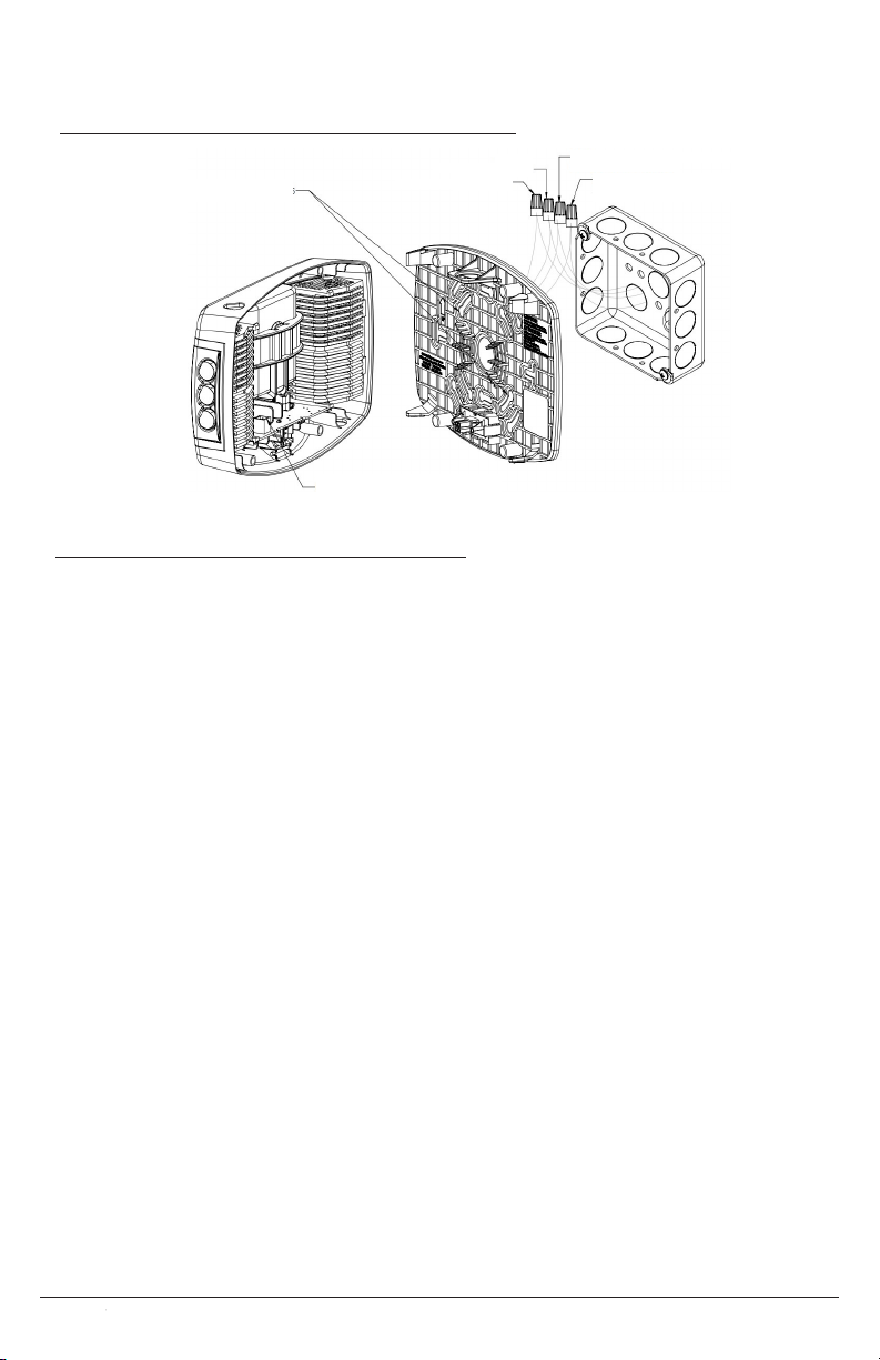
1. Remove the cover by pressing the snap tabs marked “Press” [FIGURE]
2. Remove the appropriate knockouts on the mounting plate for the selected junction box.
3. Connect the xture wires to the power supply wires using the provided wire nuts. The wiring
is as follows [FIGURE]
9W Unit
Orange Wire – 277 VAC Input
Black Wire – 120 VAC Input
White Wire – Neutral
16W Unit
Black Wire – 120-277VAC Universal Input
White Wire – Neutral
Blue Wire – Remote Lamp Negative (–)
Yellow Wire – Remote Lamp Positive (+) (9.6VDC)
4. Attach the mounting plate to the junction box via the previously established holes.
5. Check the mounting plate for level before moving on.
6. Snap the front housing onto the back housing by laying the housing on the top snaps, then
rotating into the bottom snaps. [gure]
a. When snapping the unit together, ensure that the plug and mating connector are
aligned so that the unit receives power.
7. Adjust the lamp heads down and outward for the designed emergency illumination.
WALL MOUNT BACK POWER FEED
1. Remove front cover by inserting at blade screwdriver into slots.
2. Remove appropriate knockout in back plate and mount back plate to J-box
3. Knockout in center of back plate and feed wires through the hole.
4. Securely backplate to J-box.
5. Connect the xture wires to the power supply wires using the wire nuts provided. Connect the
white wire to neutral, connect the black wire to the hot lead. Cap the unused lead. Press the
wires into the J-box (Refer to Wiring diagram below).
6. Connect remote wires if this item with remote capability. Refer to below instructions for
remote wires.
7. Plug battery male connector into battery female connector on PCBA.
8. Snap the front cover on the back plate.
9. Restore power and press test button. LED heads will turn on.
10. Adjust the lamp heads direction as needed.
MOUNTING INSTRUCTIONS
EVENLITE WWW.EVENLITE.COM Z410201